BioImpacts. 8(4):271-279.
doi: 10.15171/bi.2018.30
Original Research
Numerical study on the impulsive growth of a gaseous plug inside a cylindrical vein with compliant coating
Mohammad T. Shervani-Tabar 1, *, Babak Farzaneh 1, Reza Ahrabi 2, Seyed E. Razavi 3
Author information:
1Center for CFD Studies on Heat Engines, Cavitational Flows, and Petroleum Industries, School of Mechanical Engineering, University of Tabriz, Iran
2Department of Interventional Radiology, Alinasab Hospital, Tabriz, Iran
3School of Mechanical Engineering, University of Tabriz, Tabriz, Iran
Abstract
Introduction
: Employing of gaseous plugs inside a vein for preventing of blood flow to the damaged or cancerous tissues has been known as a gas embolism in the medicine. In this research, a numerical investigation has been carried out on the delivery of the liquid drug DDFP, encapsulated in the microlipidcoated spheres (MLCSs), to target the human vein for construction of the gaseous plug inside the veins.
Methods
: The encapsulated liquid drug DDFP were delivered to the vein by injection of an emulsion. Releasing of the liquid drug DDFP results in an explosive growth of a gaseous plug inside the vein. The targeted vein was served as a rigid cylinder with a compliant coating. The boundary integral equation method has been employed for the numerical simulation of the hydrodynamic behavior of the gaseous plug inside the vein.
Results
: Numerical results showed that in the case of a rigid cylinder vein with an internal compliant coating, the maximum volume of the gaseous plug was smaller than the case of just a rigid cylinder vein. Furthermore, its elapsed time from the instant of bubble generation to the instant when the bubble reaches its maximum volume was shorter. Numerical results also showed that the compliant coating on the internal wall of the rigid cylindrical vein had a tendency of reducing the impact of the explosive growth of the gaseous plug.
Conclusion
: This numerical research showed that the compliant coating on the internal wall of the rigid cylindrical vein had the tendency of reducing the impact of the impulsive growth of the gaseous plug. Therefore, in the case of having severed arteriosclerosis, treatment of the cancerous or damaged tissues by use of the gaseous embolism must be done very carefully in order to prevent the hazardous effects of the gaseous plug’s impulsive growth.
Keywords: Gaseous plug, Impulsive growth, Embolism, Boundary integral equation, Cylindrical vein, Compliant coating
Copyright and License Information
© 2018 The Author(s)
This work is published by BioImpacts as an open access article distributed under the terms of the Creative Commons Attribution License (
http://creativecommons.org/licenses/by-nc/4.0/). Non-commercial uses of the work are permitted, provided the original work is properly cited.
Introduction
Embolism has been widely used in medicine for killing or deactivating of the cancerous or damaged tissues. Recently, Bull
1
has introduced the gaseous embolism by using the liquid drug dodecaflouropentane (DDFP) encapsulated in the lipid-coated microspheres. The liquid drug DDFP is in the state of the superheated gas at the temperature of the human body. Therefore, through the emission of the ultrasound waves focused on a specified point inside the targeted vein, it is possible to rapture the lipid coating of the microspheres and releasing of the required amount of the liquid drug DDFP. Since the liquid drug is in the state of the superheated gas at the temperature of human body, then the released liquid drug at a specified point inside the targeted vein can cause the explosive growth of a gaseous plug.
Farzaneh et al
2
have used 3 different thermodynamic processes for the explosive growth of a gaseous plug inside a targeted vein. They assumed that the targeted vein is a cylinder with a rigid wall. Based on their numerical results, they have clearly specified the required volume of the gaseous plug inside any vein of the human body for killing or deactivating of a cancerous or damaged tissue. Then, they specified the required dose of the liquid drug DDFP that should be released inside the targeted vein. This specificity can aid for emission of the ultrasound waves. Eshpuniyani et al
3
have developed a boundary element method for numerically capturing the dynamic behavior of microbubble with and without considering the contact angle hysteresis. They have shown that the initial rapid contraction or expansion of the bubbles to achieve the local equilibrium with the surrounding pressure field results in the cusps or the bulges in the normal stress profiles on the wall. They have also examined the effectiveness of bubbles in occluding flow through the channel. Wadhwa et al
4
have investigated the role of gravity in a novel cancer treatment by employing the gas embolotherapy. They have studied the evolution dynamics of two bubbles sticking to and sliding on the opposite walls of a 2D channel under the gravity-driven flow resulting from the evolution of the two bubbles. Calderon et al
5
have employed a boundary element model for (1) the development of a gas embolotherapy technique, and (2) for a selective occlusion of a blood flow to tumors. They investigated the potential of the oscillating bubble to induce flow recirculation and to impact high stresses on the vessel endothelium. The other researchers also reported very significant results about their experimental, theoretical and numerical investigations on the evolution of acoustically vaporized microdroplets in gas emboli therapy,
6
and acoustic droplet vaporization therapeutic and diagnostic applications.
7,8
Furthermore among the other reported researches in the field of the gaseous embolism, one can refer to Samuel et al,
9
Valassis et al,
10
Kripfigans et al,
11
Qamar et al,
12
Martz et al
13
and Giesecke and Hynynen.
14
In this paper, the targeted vein of the human body has been assumed to be a rigid cylinder with a compliant coating on its internal wall. Three different coatings with different elastic characteristics have been assumed for the understanding of the effects of the compliant coating on the dynamic behavior of the gaseous plug during its explosive growth phase inside the targeted vein. The boundary integral equation technique has been employed for the numerical simulation of the problem.
Materials and Methods
Geometry of the problem
The targeted vein of a human body within which the dynamic behavior of the explosive growth of a gaseous plug has to be investigated was assumed to have a cylindrical shape. At the first step the cylindrical vein was considered as a rigid wall, and it has a rigid wall with an internal compliant coating. Fig. 1 illustrates the schematic presentation of a rigid cylindrical vein, while Fig. 2 illustrates a rigid cylindrical vein with an internal compliant coating. The axis of symmetry is indicated by z and is along the length of the cylinder, while r represents the radial axis.
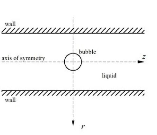
Fig. 1.
Schematic presentation of a rigid cylindrical vein.
.
Schematic presentation of a rigid cylindrical vein.
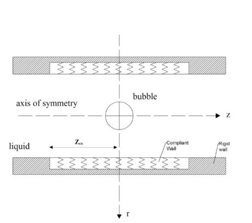
Fig. 2.
Schematic presentation of a rigid cylindrical vein with an internal compliant coating.
.
Schematic presentation of a rigid cylindrical vein with an internal compliant coating.
Hydrodynamic equations of the problem
The liquid domain inside the cylindrical vein has been assumed to be inviscid, incompressible, and irrotational. The liquid around the bubble is actually blood if the bubble is gaseous plug inside a vein of the human body. But in this research for simplicity, the liquid around the bubble was assumed as water and then its viscosity was very low and could be neglected. Then by considering the liquid flow around the gaseous plug as an incompressible irrotational flow, we can assume the liquid around the gaseous plug as potential flow and employ the Green’s integral formula and boundary element method. The assumption of potential flow around and inside the veins of the human body in complex problems was an acceptable assumption.
15
Therefore, the liquid flow around the gaseous plug was assumed to be a potential flow. Thus, the Green’s integral formula was given as the governing hydrodynamic equation of the problem, where Sgp the boundary of the gaseous was plug and Scw was the internal wall of the cylindrical vein:
(Eq. 1)
The internal wall of the cylindrical vein has been continued up to the physical infinity, where the explosive growth of the bubble has negligible effect on the hydrodynamic behavior of the liquid domain around the bubble. In equation (1), φ is the velocity potential, p is any point on the boundary or inside of the liquid domain, q is any point on the boundary, and n is the normal direction to the boundary and
The unsteady Bernoulli equation provides the possibility for evaluation of the velocity potentials on the boundaries of the liquid domain at any instant as time advances and is given in the Eulerian form as:
(Eq. 2)
Since in this problem the bubble size was very small, the buoyancy forces were negligible. The Lagrangian form of the unsteady Bernoulli equation which must be employed on the moving boundaries is given as:
(Eq. 3)
In equations (2) and (3), Pw is the pressure on the internal wall of the cylindrical vein, P∞ is the pressure at the far field, ρ is the liquid density, g is the gravity acceleration, and r represents the distance from the axis of symmetry.
Mathematical modeling of the dynamic behavior of a compliant coating
For the purpose of more realistic mathematical modeling of a vein of the human body, a compliant surface was assumed as an internal coating of the rigid cylindrical vein. The compliant coating has been assumed to be a thin rigid plate-spring model and the mathematical equation of its dynamic behavior has been given as:
(Eq. 4)
Equation (4) has been employed by Carpenter and Garrad
16
and the other researchers
17-20
to simulate Kramer-type coatings. This relatively simple model contains characteristics of a broad range of surfaces. Equation (4) mathematically models the translational displacement of a Kramer type compliant coating and has been given in the Cartesian coordinates. This equation provides the geometrical data for that part of the half axisymmetric profile of the gaseous plug which is attached to the compliant coating. Once the geometrical shape of the gaseous plug’s axisymmetric half profile was obtained, and used in the axisymmetric form of the Green’s integral formula. T is the longitudinal tension and B is the flexural rigidity of the thin plate. Also, m is the mass per unit area, d is the damping coefficient, K is the spring constant and f is the external forcing term.
In this research, the compliant wall was assumed to be cylindrical, which was attached to the internal surface of a rigid cylinder. The cylindrical compliant coating was attached to the rigid boundary along its outer edges. By assuming a very thin membrane and by ignoring the effect of damping, the equation of the cylindrical compliant coating may be written in the form of:
(Eq. 5)
Where,η =η (r,t) is the translational displacement of the cylindrical compliant coating which is in the radial direction and towards or away from the axis of symmetry. Pw is the pressure on the compliant surface. In the absence of the bubble, for (t≤ 0) the springs are compressed uniformly due to the steady uniform pressure, P∞ exerted by the internal liquid domain of the cylinder. The displacement of the thin cylindrical plate at this instant has been taken as zero. The cylindrical thin plate was attached to the rigid wall at z = ± zcs, so the inward or outward radial displacements of the thin plate at z = ± zcs were zero. During the explosive growth phase of the gaseous plug, the liquid domain inside the cylindrical vein and the surface of its internal compliant coating were coupled using the linearized equation for the pressure and the velocity in the both systems of the liquid domain inside the cylindrical vein and the surface of the compliant coating that attached to its internal wall. These equations which are satisfied at the undisturbed position of the internal surface of the cylindrical compliant coating,(r=rcs) , are:
(Eq. 7)
It should be noted that Equation (7) is the linearized unsteady Bernoulli equation.
Geometrical and mathematical discretization
The boundary of the gaseous plug was discretized by the cubic spline elements, whereas the internal surface of the cylindrical vein was discretized by the linear segments.
Fig. 3A illustrates the discretized geometry of the problem, when the cylindrical vein was assumed as a rigid cylinder. The z-axis along the cylinder length was the axis of symmetry and discretization on the internal wall of the rigid cylinder along the z-axis was continued from both left- and right sides of the gaseous plug until the points in the far field. The points in the far field are wherever that the explosive growth of the gaseous plug has negligible effects on the hydrodynamic behavior of the liquid domain.
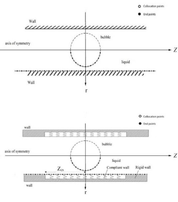
Fig. 3.
Schematic discretization of the geometry in the case of (A) gaseous plug inside a vertical rigid vein, (B) gaseous plug inside a vertical rigid vein with a compliant coating (hollow circles indicate the end points of the elements and black circles represent the colocation points).
.
Schematic discretization of the geometry in the case of (A) gaseous plug inside a vertical rigid vein, (B) gaseous plug inside a vertical rigid vein with a compliant coating (hollow circles indicate the end points of the elements and black circles represent the colocation points).
Fig. 3B illustrates the discretized geometry of the problem when the vein has been assumed to be a rigid cylinder with an internal compliant coating. As it is stated in the case of Fig. 3A, the boundary of the gaseous plug has been discretized by the cubic spline elements and the internal wall of the cylindrical vein, which has a compliant coating around the explosive growing gaseous plug, was discretized by the linear segments. The height of the cylindrical compliant coating was 2.5 times of the maximum diameter of the gaseous plug and its outer edge was attached to the rigid wall from its both left- and right sides. The surface of the gaseous plug is discretized by the cubic spline elements and the internal wall of the cylindrical vein is discretized by the linear segment. The boundary conditions for the cubic spline elements over the gaseous plug surface were clamped boundary conditions and the first and last cubic spline elements over the half profile of the gaseous plug must be tangential to any line parallel to the axis of r. The geometrical characteristics of the problem have been non-dimensionalized by the equivalent maximum radius of the plug. Due to the significant importance of the discretization in the numerical simulations, the gird independency was considered.
As it can be seen in Fig. 4, the numerical procedure has been done for four different number of nodes in order to gain grid independence. Fig. 4 shows that the numerical results for the case of N=300 and N=380 are almost the same. On this base, discretization with N=300 nodes has been chosen as standard discretization and the problem has been solved with the discretization of 300 nodes. In the case of the rigid cylindrical vein, the grid independence, which has been discussed in Fig. 4, is enough for considering the stability of the problem. But in the case of having a compliant surface the size of the element on the compliant surface in the direction of z-axis becomes a more critical problem due to the Tolliman-Schilichting instability. In this case, Δz must be as small as possible in a manner that discretized compliant surface could follow the wavelength of the disturbed wavy compliant wall.
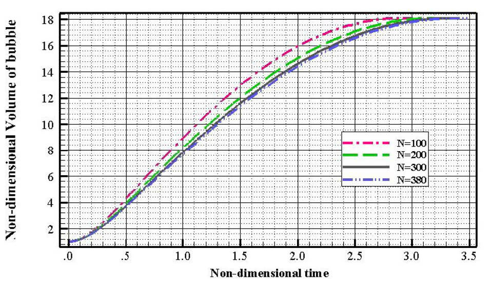
Fig. 4.
Grid independency of the numerical simulation .
.
Grid independency of the numerical simulation .
The hydrodynamic equations represent the mathematical models for the dynamic behaviors of the gaseous plug and the liquid domain in it’s around have been discretized as:
(Eq. 8)
(Eq. 9)
(Eq. 10)
Where equation (8) represents discretization of the Green’s integral formula and M is the number of cubic splines on the bubble surface and MN is the number of total segments on the bubble surface and the internal wall of the cylindrical vein. Equations (9) and (10) and represent discretization of the Eulerian and Lagrangian forms of the unsteady Bernoulli equation, respectively.
The mathematical model of the dynamic response of the compliant coating to its nearby liquid domain behavior has been discretized as:
(Eq. 11)
Since equation (11) represents an explicit discretized equation, then attempts have been done for obtaining the stability conditions of this scheme. Therefore the time step for the evolution of the problem and ∆z along the internal surface of the cylindrical vein, have been chosen in a manner that has satisfied the stability conditions of this explicit scheme.
The boundary conditions for the numerical solution of equation (11) are
at z=0 and η=0 at z=±zcs. The former boundary condition is because of the symmetry, while the latter boundary conditions are because of the attachment of the compliant coating to the rigid wall.
Numerical implementation
By having the distribution of the normal velocity on the internal surface of the cylindrical vein and by having the distribution of the velocity potential on the boundary of the gaseous plug, the Green’s integral formula provides the solution for obtaining normal velocity on the boundary of the gaseous plug at any instance as well as velocity potential on the internal surface of the cylindrical vein. In the case of having a rigid cylindrical vein, the normal velocity on its internal surface is known and is equal to zero. Also according to Best
21
the velocity potential on the boundary of an explosive growing bubble at the instant of its initial minimum volume is known and is equal to zero as well. Then, as it is stated above, the Green’s integral formula provides the solution for obtaining the velocity potential on the internal surface of the rigid cylindrical vein and the normal velocity on the boundary of the gaseous plug. For the next time step, the velocity potential on the boundary of the gaseous plug can be obtained from the discretized unsteady Bernoulli equation. Furthermore, the normal velocity on the internal surface of the rigid cylindrical vein is known at every time step and is equal to zero.
Therefore by definition of a variable time step as:
(Eq. 12)
The numerical simulation of the explosive growth of a gaseous plug inside a rigid cylindrical vein can proceed through its elapsed time from the instant of bubble generation to the instant when the bubble reaches its maximum volume. In equation (12) that comes from the discretized unsteady Bernoulli equation and has been modified by choosing the value of Pgp + P∞ instead of the pressure difference of Pgp – P∞, ∆φ is some constant and is equal to the maximum difference of the velocity potential on the boundary of the gaseous plug between two successive time steps.
The discretized forms of the equations which provide the boundary conditions at the liquid domain-compliant surface interface are given as:
(Eq. 13)
and
(Eq. 14)
Solution strategy for the case of a rigid cylindrical vein with an internal compliant coating
If the vein has been assumed as a rigid cylinder with an internal compliant coating, the velocity and displacement of any point on the surface of the compliant coating have to be obtained from equation (5) which represents the mathematical model of a thin spring-backed compliant surface. On the other hand equation (5) needs to have the initial distribution of the pressure on the compliant surface at the initial instant of the explosive growth of the gaseous plug for starting of the solution. But the initial pressure distribution on the compliant surface at the initial instant of the explosive growth of the gaseous plug is not known. The initial pressure distribution on the compliant surface has to be found from the acceleration of the surface of the compliant coating at the initial instant of the problem. Furthermore, it should be noted that the acceleration of the surface of the compliant coating can be calculated from equation (5) which needs to have the distribution of the pressure on its surface. Therefore, the unknown physical parameters of the problem are one more than the known physical parameters. Consequently, the numerical simulation of the problem under investigation in the case of the explosive growth of a gaseous plug inside a rigid cylinder with an internal compliant coating is not possible unless an iteration scheme has been employed for obtaining the initial distribution of the pressure on the surface of the compliant coating.
In this study, an iteration scheme which has been proposed by Duncan and Zhang
22
for a collapsing cavitation bubble from its maximum volume and adapted by Shervani-Tabar
23
for an explosion bubble growing from its initial minimum volume has been employed for the numerical simulation of interaction of the dynamic behavior of the liquid domain around the gaseous plug and the dynamic reaction of the internal compliant coating of the cylindrical vein.
Non-dimensionalizing of the numerical solution
The numerical solution of the problem has been non-dimensionalized by Rm, the maximum radius of the gaseous plug, as a scale for any length,
as a scale for time,
as a scale for velocity potential and
as a scale for velocity.
The non-dimensional parameters which identify the elastic characteristics of the compliant coatings are defined as:
Results
In this study, a numerical investigation of the explosive growth of a gaseous plug due to the releasing of the liquid drug DDFP inside a cylindrical vein has been carried out in four different cases. In all cases, the amount of the releasing liquid drug is the same. In the first case, the vein has been assumed to be a rigid cylinder, while in the 3 other cases the vein has been assumed to be a rigid cylinder with an internal compliant coating. The elastic characteristics of the internal compliant coating have been assumed to be different in the latter 3 cases. The non-dimensional elastic characteristics of the internal compliant coatings in the latter 3 cases have been assumed as follows:
(Compliant surface A): M*=160, K*=160 and T*=0.0025,
(Compliant surface B): M*=60, K*=60 and T*=0.0025,
(Compliant surface C): M*=25, K*=25 and T*=0.0025.
It should be noted that the compliant surface C is softer than the compliant surface B and the compliant surface B is softer than the compliant surface A.
The numerical results of this study have been verified with the experimental work of Farhangmehr.
24
As it can be seen in the Fig. 5, the numerical result of this investigation about the variation of the equivalent radius of the vapor bubble inside a rigid cylinder with respect to the time in the case of is λ=1 in good agreement with the experimental results of Farhangmehr.
24
Where λ is the ratio of the radius of the cylindrical vein to the equivalent maximum radius of the gaseous plug.
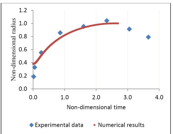
Fig. 5.
Bubble radius growth with respect to time (a comparison between numerical and experimental data)
.
Bubble radius growth with respect to time (a comparison between numerical and experimental data)
Fig. 6 illustrates variations of the non-dimensional volume of the gaseous plug with respect to the non-dimensional time for the cases of 3 different compliant coatings and also for the case of a rigid cylindrical vein. The non-dimensional volume of the gaseous plug is the ratio of the plug’s volume to each initial minimum volume at every time step. Fig. 6 clearly shows that the rate of growth the gaseous plug with respect to the time in the case of considering the compliant surface C is much higher than the other cases. It means that the dynamic response of the compliant coating C to the explosive growth phase of the gaseous plug through its considerable displacement facilitates the plug’s growth. This figure also shows that in the cases of a rigid cylindrical vein with an internal compliant coating, the maximum volume of the gaseous plug at the end of its growth phase is smaller than the case of having a rigid cylindrical vein. It should be noted that in all cases of this investigation, the amount of the liquid drug which has been released inside the targeted vein is the same.
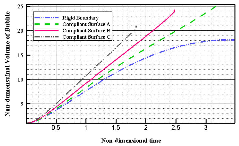
Fig. 6.
Variations of the ratio of the bubble volume at any instance to its initial volume with respect to the non-dimensional time.
.
Variations of the ratio of the bubble volume at any instance to its initial volume with respect to the non-dimensional time.
Fig. 7 illustrates the non-dimensional velocity of the midpoint of the internal wall of the cylindrical vein with respect to the non-dimensional time in the cases of 3 different internal compliant coatings. Fig. 7 clearly illustrates that the rate of variation of the non-dimensional velocity of the center point of the compliant surface C with respect to time has considerable higher magnitude than the cases of compliant surfaces A and B especially during the early stages of the growth phase of the gaseous plug. It means that the acceleration which the central point of the compliant surface C gains due to the impulsive growth of the gaseous plug is much higher than the two other compliant surfaces especially at the initial stages of the growth phase.
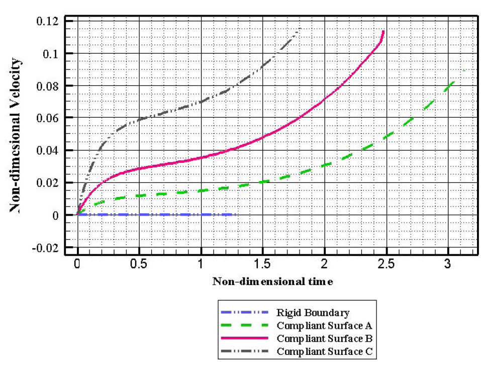
Fig. 7.
Variations of the non-dimensional velocity of the center of internal compliant coating of the cylindrical vein with respect to the non-dimensional time.
.
Variations of the non-dimensional velocity of the center of internal compliant coating of the cylindrical vein with respect to the non-dimensional time.
Fig. 8 illustrates the non-dimensional displacement of the midpoint of the 3 different internal compliant coatings of the cylindrical vein during the explosive growth of the gaseous plug with respect to the non-dimensional time. As it has been shown in Fig. 8, the midpoint of the compliant surface C has the maximum displacement and the time which this maximum displacement takes to achieve is the shortest. It means that the considerable response of the compliant surface C to the plug’s explosive growth phase reduces confinement of the space around the surrounding liquid of the gaseous plug and consequently facilitates its explosive growth phase shortens its elapsed time from the instant of bubble generation to the instant when the bubble reaches its maximum volume.
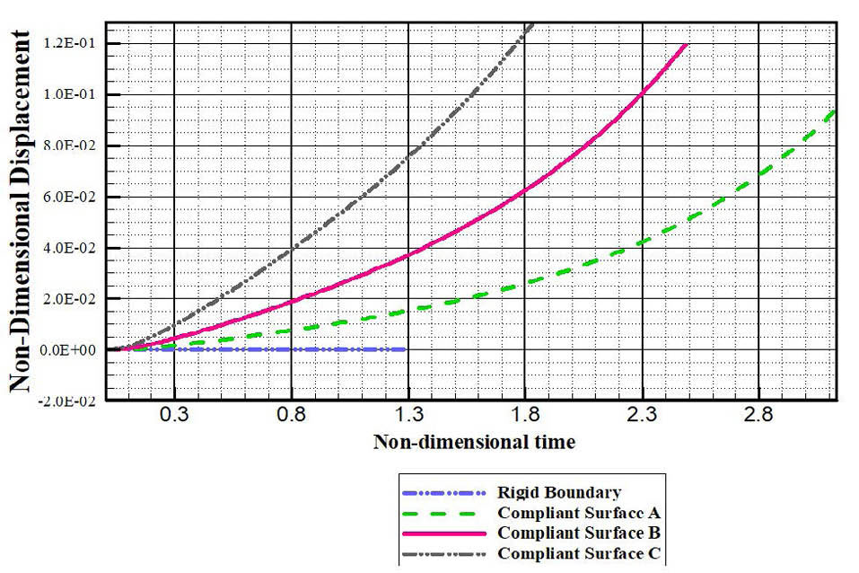
Fig. 8.
Variations of the non-dimensional displacement of the center of the internal compliant coating of the rigid cylindrical vein with respect to the non-dimensional time.
.
Variations of the non-dimensional displacement of the center of the internal compliant coating of the rigid cylindrical vein with respect to the non-dimensional time.
Fig. 9 illustrates the pressure distribution on the internal wall of the cylindrical vein due to the explosive growth of the gaseous plug at the earliest stages of its growth phase in four different cases of the investigation. This figure shows that in the case of having a rigid cylindrical vein the maximum pressure on the nearest point of the vein’s internal wall to the gaseous plug has the highest value. This figure also shows that the difference between the pressure on the nearest point of the vein’s internal wall to the gaseous plug and the pressure on the far point on the vein’s internal wall from it has the highest magnitude when the vein has been assumed to be a rigid cylinder. Whereas, in the case of having the compliant surface C as the internal compliant coating, the pressure difference between the nearest point of the vein’s internal wall to the plug and the far point on the vein’s internal wall from it has the lowest magnitude. It means that the compliant surface C through its considerable response to the impulsive force resulted from the gaseous plug’s impulsive phase propagates this explosive force along the z-axis.
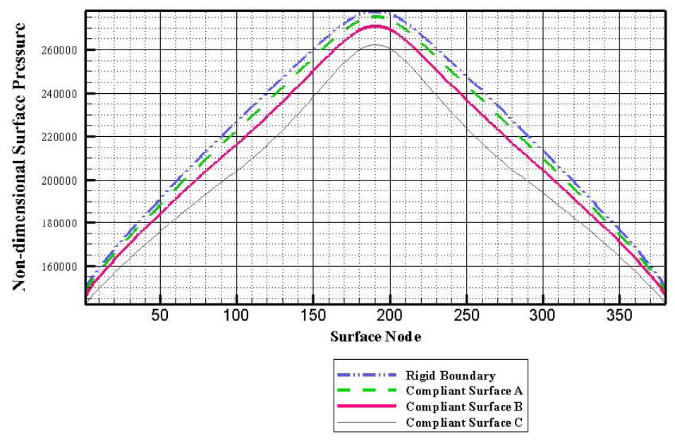
Fig. 9.
The initial pressure distribution on the internal surface of the cylindrical vein at the earliest stages of the explosive growth of the gaseous plug in 4 different cases.
M
*is the ratio of the mass per unit area of membrane to an equivalent mass per unit area of the liquid based on a thickness of Rm. K* is the ratio of the spring term in the membrane equation to the pressure difference driving the explosive growth of the gaseous plug. T* is the ratio of the tension term in the membrane equation to the pressure difference which drives the explosive growth of the gaseous plug.
.
The initial pressure distribution on the internal surface of the cylindrical vein at the earliest stages of the explosive growth of the gaseous plug in 4 different cases.
M
*is the ratio of the mass per unit area of membrane to an equivalent mass per unit area of the liquid based on a thickness of Rm. K* is the ratio of the spring term in the membrane equation to the pressure difference driving the explosive growth of the gaseous plug. T* is the ratio of the tension term in the membrane equation to the pressure difference which drives the explosive growth of the gaseous plug.
Fig. 10 illustrates the pressure distribution on the internal wall of the cylindrical vein due to the explosive growth of the gaseous plug at the latest stages of the gaseous plug’s growth phase. Fig. 10 clearly shows that the pressure distribution on the internal wall of the cylindrical vein in the case of the compliant surface C as the internal coating is more uniform than the case of having a rigid cylindrical vein. This is due to the displacement of the compliant surface C which has a considerable magnitude in comparison with compliant surfaces A and B.
Fig. 10 shows the bubble shape history during its elapsed time from the instant of bubble generation to the instant when the bubble reaches its maximum volume inside a rigid cylindrical vein with λ=1. As it is shown in Fig. 11 the bubble at the initial instant of its explosive growth phase has a spherical shape. This figure clearly showed that the gaseous plug during its explosive growth phase elongates in cylindrical vein z-axis. But at the final stages, both two extreme sides of the gaseous plug along the z-axis were flattened.
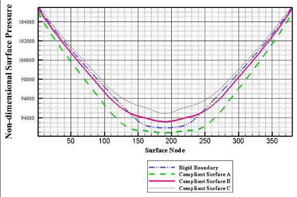
Fig. 10.
Pressure distribution on the internal surface of the
cylindrical vein at the latest stages of the gaseous plug’s explosive
growth phase in 4 different cases.
.
Pressure distribution on the internal surface of the
cylindrical vein at the latest stages of the gaseous plug’s explosive
growth phase in 4 different cases.
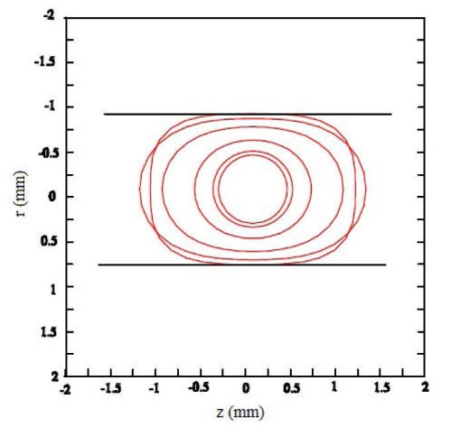
Fig. 11.
Bubble shape history during its elapsed time from the
instant of bubble generation to the instant when the bubble
reaches its maximum volume.
.
Bubble shape history during its elapsed time from the
instant of bubble generation to the instant when the bubble
reaches its maximum volume.
Discussion
In this paper, a numerical investigation has been carried out for understanding the dynamic behavior of a gaseous plug during its explosive growth inside a rigid cylindrical vein without and with an internal compliant coating. Initially, the vein was assumed as a rigid cylinder and then as a rigid cylinder with a compliant coating on its internal wall. In the latter cases, the dynamic behavior of the gaseous plug during its explosive growth phase inside a cylindrical vein was studied in 3 different cases by assuming different internal compliant coatings with different elastic characteristics in each case.
The numerical results showed that, by releasing a specified amount of the liquid drug DDFP, the lifetime of the growth of the gaseous plug, when the vein counted as a rigid cylinder, was the longest and its volume at the end of the growth phase was the largest. Whereas, in the case of the compliant surface C, as the internal coating of the cylindrical vein the lifetime of the growth of the gaseous plug was the shortest and its volume at the end of the growth phase was the smallest. Therefore, by releasing the same amount of the liquid drug DDFP inside a vein, the time of vanishing of the gaseous plug inside the rigid cylindrical vein was longer than the time that takes for the vanishing of the gaseous plug inside a vein with an internal compliant surface.
It is found that the maximum pressure on the internal wall of the rigid cylindrical vein at the closest point to the gaseous plug at the earliest stages of the growth phase of the plug has the highest magnitude. Whereas, in the case of having the compliant surface C as the internal coating of the cylindrical vein, the maximum pressure on the internal wall of the vein at the earliest stages of the gaseous plug’s growth phase has the lowest magnitude.
Numerical results also showed that, at the latest stages of the growth of the gaseous plug, the maximum pressure difference on the internal wall of the vein between the closest point to the gaseous plug and the point far from it has the largest magnitude in the case of the rigid cylindrical vein. Whereas the compliant surface C, when has been assumed as the internal coating of the rigid cylindrical vein, provides more uniform pressure distribution on the internal wall of the vein due the explosive growth of the gaseous plug at the latest stages of its growth phase.
Therefore, it is found that the compliant coating on the internal wall of the rigid cylindrical vein has the tendency of reducing the impact of the explosive growth of the gaseous plug. It was also found that the effect of the internal compliant coating of the rigid cylindrical vein on the behavior of the gaseous plug during its growth phase is through the dynamic response of the compliant coating to its nearby liquid domain that results in absorbing of energy from the liquid domain.
Acknowledgments
None.
Funding sources
None.
Ethical statement
There is none to be declared.
Competing interests
The authors declare no conflict interests.
Authors contribution
The article is part of a PhD thesis which has been submitted to the university of Tabriz as partial requirement for a PhD degree. The main idea is from MTST, as the principal adviser and supervisor of the PhD candidate, and he has provided the main computer code for discretization of the problem via the boundary integral equation method. BF, as the PhD candidate, together with MTST have provided computer subroutines to the main computer code for numerical simulation of the problem under investigation. RA, as the second adviser of the PhD candidate, has contributed to the article by collecting the experimental data. SER has contributed to the article as the third adviser of the PhD candidate.
Research Highlights
What is the current knowledge?
simple
-
√ Hydrodynamic behavior of the generation of the gaseous
plugs inside veins of the human body.
What is new here?
simple
-
√ Evaluation of impulsive pressure due to the explosive
growth of a gaseous plug inside a cylindrical vein with a
compliant coating on the different internal coating surfaces.
-
√ Evaluation of elapsed time from the instant of bubble
generation to the instant when the bubble reaches its
maximum volume of the plug’s growth phase in the vicinity
of different internal coating surfaces..
-
√ The translational importance of the main findings in this
research is evaluating of the magnitude of the liquid drug
DDFP which must be released inside the targeted vein and
can generate a specified size of a gaseous plug for killing or
deactivating of the cancerous or damaged tissues.
References
- Bull JL. Cardiovascular bubble dynamics. Crit Rev Biomed Eng 2005; 33(4):299-346. doi: 10.1615/CritRevBiomedEng.v33.i4.10 [Crossref] [ Google Scholar]
- Farzaneh B, Shervani-Tabar MT, Ahrabi R, Razavi SE. Dynamic behavior of gaseous plug in treatment of cancerous tumors by embolism. J Acta Technica 2017.
- Eshpuniyani B, Fowlkes JB, Bull JL. A boundary element model of microbubble sticking and sliding in the microcirculation. Int J Heat Mass Transf 2008; 51:5700-11. doi: 10.1016/j.ijheatmasstransfer.2008.04.050 [Crossref] [ Google Scholar]
- Wadhwa N, Jain V, Fowlkes JB, Bull JL, Eshpuniyani B. A boundary element model of multiple microcirculatory bubbles in cardiovasculature. Int J Emerg Multidiscip Fluid Sci 2010; 2(2-3):143-160. doi: 10.1260/1756-8315.2.2-3.143 [Crossref] [ Google Scholar]
- Calderón AJ, Fowlkes JB, Bull JL. Bubble splitting in bifurcating tubes: a model study of cardiovascular gas emboli transport. J Appl Physiol 2005; 99:479-87. doi: 10.1152/japplphysiol.00656.2004 [Crossref] [ Google Scholar]
- Kripfigans OD, Fowlkes JB, Miller DL, Eldevik OP, Carson PL. Acoustic droplet vaporization for therapeutic and diagnostic applications. Ultrasound Med Biol 2000; 26:1177-89. doi: 10.1016/S0301-5629(00)00262-3 [Crossref] [ Google Scholar]
- Kagan D, Benchimol MJ, Claussen JC, Chuluun‐Erdene E, Esener S, Wang J. Acoustic Droplet Vaporization and Propulsion of Perfluorocarbon‐Loaded Microbullets for Targeted Tissue Penetration and Deformation. Angew Chem Int Ed Engl 2012; 124:7637-40. doi: 10.1002/anie.201201902 [Crossref] [ Google Scholar]
- Zhou Y. Application of acoustic droplet vaporization in ultrasound therapy. J Ther Ultrasound 2015; 3:20. doi: 10.1186/s40349-015-0041-8 [Crossref] [ Google Scholar]
- Samuel S, Duprey A, Fabiilli ML, Bull JL, Brian Fowlkes J. In vivo microscopy of targeted vessel occlusion employing acoustic droplet vaporization. Microcirculation 2012; 19:501-9. doi: 10.1111/j.1549-8719.2012.00176.x [Crossref] [ Google Scholar]
- Valassis DT, Dodde RE, Esphuniyani B, Fowlkes JB, Bull JL. Microbubble transport through a bifurcating vessel network with pulsatile flow. Biomed Microdevices 2012; 14:131-43. doi: 10.1007/s10544-011-9591-x [Crossref] [ Google Scholar]
- Kripfigans OD, Fabiilli ML, Carson PL, Fowlkes JB. On the acoustic vaporization of micrometer-sized droplets. J Acoust Soc Am 2004; 116:272-81. doi: 10.1121/1.1755236 [Crossref] [ Google Scholar]
- Qamar A, Wong ZZ, Fowlkes JB, Bull JL. Dynamics of acoustic droplet vaporization in gas embolotherapy. Appl Phys Lett 2010; 96:143702. doi: 10.1063/1.3376763 [Crossref] [ Google Scholar]
- Martz TD, Sheeran PS, Bardin D, Lee AP, Dayton PA. Precision manufacture of phase-change perfluorocarbon droplets using microfluidics. Ultrasound Med Biol 2011; 37:1952-7. doi: 10.1016/j.ultrasmedbio.2011.08.012 [Crossref] [ Google Scholar]
- Giesecke T, Hynynen K. Ultrasound-mediated cavitation thresholds of liquid perfluorocarbon droplets in vitro. Ultrasound Med Biol 2003; 29:1359-65. doi: 10.1016/S0301-5629(03)00980-3 [Crossref] [ Google Scholar]
- Farhangmehr V, Aghdam AH, Shervani-Tabar MT, Parvizi R, Ohl S, Khoo B. Numerical investigation on the pulsating bubble dynamics in a narrow cylinder with a compliant coating. Fluid Dyn Res 2014; 46:015513. doi: 10.1088/0169-5983/46/1/015513 [Crossref] [ Google Scholar]
- Carpenter P, Garrad A. The hydrodinamic stability of flow over Kramer-type surfaces Part 1 Tollmien-Schlichting instabilities. J Fluid Mech 1985; 155:465-510. doi: 10.1017/S0022112085001902 [Crossref] [ Google Scholar]
- Soh WK. An energy approach to cavitation bubbles near compliant surfaces. Appl Math Model 1992; 16:263-8. doi: 10.1016/0307-904X(92)90018-X [Crossref] [ Google Scholar]
- Shervani-Tabar MT, Rezaee M, Madadi-Kandjani E. Perfect plastic deformation of a circular thin metal plate due to pulsation of a vapour bubble. IJMS 2013; 75:345-56. doi: 10.1016/j.ijmecsci.2013.08.001 [Crossref] [ Google Scholar]
-
Shervani-Tabar MT, Shabgard MR, Rezaee M, Zabihyan R. Dynamics of a vapour bubble near a thin elastic plate. 7th International Symposium on Cavitation (cav 2009); 16-20 August 2009; Ann Arbor, Michigan, USA. pp. 402-414.
- Blake JR, Gisbon DC. Cavitation bubbles near boundaries. Ann Rev Fluid Mech 1987; 19:99-123. [ Google Scholar]
-
Best JP. The dynamics of underwater explosions. [Philosophy thesis]. 1991.
- Duncan J, Zhang S. On the interaction of a collapsing cavity and a compliant wall. J Fluid Mech 1991; 226:401-23. doi: 10.1017/S0022112091002446 [Crossref] [ Google Scholar]
-
Shervani-Tabar MT. Computer study of a cavity bubble near a rigid boundary, a free surface, and a compliant wall [PhD thesis]. Australia: Departement of Mechanical Engineering, University of Wollongong; 1995.
-
Farhangmehr, V. Numerical and experimental investigation on the latest stages of a cavitation bubble collapse inside vertical rigid cylinder with an without compliant coating [PhD thesis]. Tabriz: Department of Mechanical Engineering, University of Tabriz; 2014.