Bioimpacts. 13(6):488-494.
doi: 10.34172/bi.2023.23809
Original Article
Towards modeling of phonation and its recovery in unilateral vocal fold paralysis by fluid-structure interaction
MohammadAmin Naseri Data curation, Formal analysis, Investigation, Resources, Software, Validation, Visualization, Writing – original draft, Writing – review & editing, 1, * 
Seyed Esmail Razavi Conceptualization, Methodology, Project administration, Supervision, 2
Author information:
1Department of Mechanical Engineering, University of Texas at Dallas, Richardson, TX, USA
2Faculty of Mechanical Engineering, University of Tabriz, Tabriz, Iran
Abstract
Introduction:
Vocal folds are responsible for sound generation. In unilateral vocal fold paralysis (UVFP), the recurrent laryngeal nerve, which controls the vocal folds, is paralyzed. Medialization laryngoplasty is a surgery in which an implant is inserted to push the paralyzed vocal fold to the centerline to recover phonation.
Methods:
Here, a numerical simulation is used to calculate flow-related parameters to give insight into what happens in healthy and treated(implanted) vocal folds and their enhancement. In the present work, airflow over vocal folds is modeled considering fluid-structure interaction (FSI) and varying inlet pressure. The governing equations are discretized for fluid and solid domains and solved using the Galerkin finite element method. The boundary conditions for healthy and unilaterally paralyzed vocal folds were imposed to agree with real cases behavior.
Results:
The results showed the effectiveness of medialization laryngoplasty in treating unilateral vocal fold paralysis concerning healthy vocal folds.
Conclusion:
This simulation provided a better insight into treatment results for patient-specific cases.
Keywords: Phonation recovery, Unilateral vocal fold paralysis, Fluid-structure interaction, Numerical simulation, Navier-stokes equations
Copyright and License Information
© 2023 The Author(s).
This work is published by BioImpacts as an open access article distributed under the terms of the Creative Commons Attribution Non-Commercial License (
http://creativecommons.org/licenses/by-nc/4.0/). Non-commercial uses of the work are permitted, provided the original work is properly cited.
Funding Statement
There are no founding sources for the present work.
Introduction
Speech is key for communication between humans. While normal phonation is a must for clear speech, a large group of people faces voice disorders. Unilateral vocal fold paralysis (UVFP) is responsible for phonation problems like breathiness and hoarseness of voice. Voice production inside the human larynx is a result of interaction between the air, which is supplied by the lungs, and vocal fold tissues which are located in the end of the trachea.
During normal phonation, both vocal folds vibrate and generate sound, but in the case of UVFP, recurrent laryngeal nerve, which is responsible for abduction and adduction of vocal folds, paralyzes. Hence, muscles of the vocal fold will have very limited movement.1
Mittal et al.2 developed a simulation-based tool to predict the optimal placement and shape of the vocal fold implant based on real-life data from laryngeal endoscopy and computerized tomography (CT) scan. They employed an open-source C++ finite element solver for the solid domain. For glottal flow, an immersed boundary method was applied, and unsteady Navier-Stokes equations were solved.
Two-dimensional models have widely been used. A prevalent model is an M5 geometry for vocal folds. Murray et al3 studied the flow-induced responses of synthetic vocal fold models and compared the measured data from their experimental model with results from human data. Measurements were performed in the full larynx and hemilarynx configurations and high-speed imaging techniques were also used. The advantages and disadvantages of the proposed models were also discussed.
Zheng et al4 studied the effect of false vocal folds (FVFs) using a 2D computational model. An immersed boundary method for airflow and a continuum finite element model for vocal folds were used. Changes in flow-induced vibrations of VF and dynamics of the glottal jet were studied. They showed that FVF reduce the glottal flow impedance and increase the magnitude and velocity of the glottal jet; hence FVF greatly influence phonation.
Bagheri et al5 numerically studied the features of flow fields in normal larynx and larynx with UVFP using ANSYS Mechanical and ANSYS CFX for structural analysis and flow field simulation. Effects of initial glottal gap on flow fields were discussed and the advantageous effects of surgery was confirmed by the results.
Svácek and Horácek6 numerically analyzed the interaction of the vibrating VF using incompressible viscous airflow in a 2D domain. The governing Navier-Stokes equations for the flow domain were written in the arbitrary Lagrangian-Eulerian (ALE) form. They investigated the effects of inflow boundary conditions as well as the geometry of the channel on phonation. Finally, they optimized the selected inlet velocity boundary condition using a penalization approach.
Švancara et al7 studied a 2D finite element model of fluid-structure-acoustic interaction during self-oscillations of VF shaped for phonation of vowel [a:]. The FSI is solved using an explicit coupling scheme with separated solvers for structure and fluid domain with ALE method. The numerical simulation results showed close similarities with real human voice production and video kymographic images created from numerical modeling results were similar to those in real human vocal folds.
Wang et al8 investigated the effects of the stiffness parameters of vocal fold layers on voice production. Using a three-dimensional model, transverse and longitudinal elastic modulus for cover, ligament and body layers were studied. Unsteady, viscous, incompressible Navier-Stokes equation was solved using an immersed-boundary method based on finite difference method. The results showed that longitudinal stiffness parameters of the ligament layer generally have more significant impacts on glottal flows.
Zheng et al9 developed a surgical/numerical model for investigation of UVFP to improve the surgical outcomes. For the computational model, a finite element method was used, where, cartilage displacements from magnetic resonance imaging (MRI) were prescribed. The VF deformation was simulated and the results for eigenfrequencies of left and right VFs were similar. However, in the UVFP condition, asymmetrical eigenfrequencies were obtained.
Here, a comparative study was done to numerically investigate the differences between healthy and treated unilaterally paralyzed VFs using fluid-structure interaction (FSI) with varying inlet pressure. Medialization laryngoplasty10 was an effort to recover phonation and was studied in the case of UVFP and the flow-related parameters like velocity, streamlines, shear stresses, pressure drops, and flow rates were identified in each case. Furthermore, eigenfrequencies, von-mises stresses, and displacements for different pressure drops were compared in both cases and separation of flow was also studied.
Materials and Methods
To study the flow over VFs, an immersed boundary method2 was applied. The computational model was taken from a commonly used geometry for VFs in 2D applications, and VFs were modeled in a 2×12 cm rectangular channel beginning at 2.2 cm from the inlet.4 The part where VFs were located was of interest and was displayed throughout the text. This region contained both VF and FVF and the rest of the channel is not displayed.
Since Mach number was less than 0.3 in human phonation, the incompressible Navier-Stokes equations were used as follows2,7:
where u denotes fluid velocity field, ρ is fluid density, and p is pressure. K represents Cauchy stress which is defined as:
The solid domain is governed by the Newton’s second law:
(4)
where fv shows body forces, F is deformation gradient, and S stands for the second Piola-Kirchhoff stress tensor as:
Considering the Hook’s law:
In which, σ denotes stress tensor and is proportional to ϵ which shows strain tensor.
Air is considered to be incompressible, Newtonian, and in a laminar regime.11 VFs are considered to be linear elastic12 and false VFs are rigid bodies. First, a pair of healthy VFs with varying inlet pressure was modeled to give a benchmark. The inlet pressures correspond to Reynolds numbers that stay within laminar region. Then, the result of inserting an implant into the paralyzed VF, with a much stiffer young modulus but a shape close to the VF geometry, in order to push it to centerline was studied. The latter case was compared with healthy VFs to study the amount of phonation recovery.
The glottal gap width is initially 0.2 mm13 but in the case of UVFP, it is not possible to obtain the desired gap width, due to paralysis of one VF, and thus, a wider gap is obtained. In neither case, the upper and lower vocal folds came into contact. The boundary conditions (BC) include a zero-gauge pressure at the outlet boundary representing the epiglottis pressure. Thus, every inlet pressure was equal to pressure drop between sub and supra glottal regions. This is equal to implementing velocity inlet BC for air.6 In order not to face convergence issues, namely, having the same glottal jet evolutions for each case of inlet pressure, varying pressure as inlet BC was smoothly implemented using a proper step function. The walls were no-slip14 and the VFs were fixed to the channel walls. The solution started with a timestep of 2×10⁻⁵ second and a 0.01 of initial timestep was chosen for algebraic solver minimum timestep to ensure the convergence.
The Galerkin finite element method15 was used for discretizing and solving the governing equations for both flow and structure domains. First order elements for both velocity and pressure fields were used. Displacement was discretized using quadratic lagrange method. The backward differentiation formula was used to provide stability for the time-stepping of numerical method. To reduce the computational costs, the inlet and outlet regions, which are of less importance, were meshed using mapped elements and the middle part of the channel, which is of interest, was meshed using unstructured triangular meshes. This dramatically improved the overall mesh quality besides reducing the total number of elements.
VFs and different layers of them are shown in Fig. 1. Cover in the outer layer was converted to the body through ligament. The material properties of each layer are shown in Table 1. A linear elastic material was applied as solid domain. For a biological material like a muscle, to handle incompressibility of solid, a Poisson’s ratio of 0.5 is used.16 However, in 2D models, a Poisson’s ratio of 0.3 is applied.13
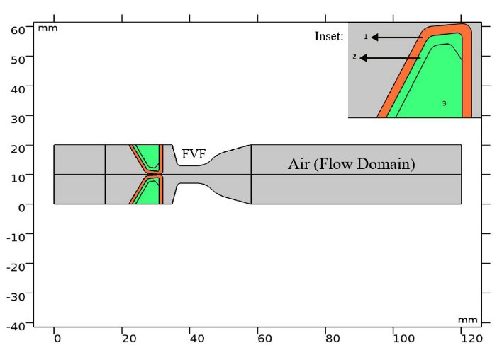
Fig. 1.
Computational domain and different layers of vocal folds with layer numbers. Inset shows vocal fold layers.
.
Computational domain and different layers of vocal folds with layer numbers. Inset shows vocal fold layers.
Table 1.
Material properties of vocal fold layers
|
Layer No.
|
Layer
|
E (KPa)
|
ρ (kg/m3)
|
v
|
| 1 |
Cover |
20 |
1043 |
0.3 |
| 2 |
Ligament |
33 |
1043 |
0.3 |
| 3 |
Body |
40 |
1043 |
0.3 |
E denotes Young’s modulus of elasticity, ρ for density, and v the Poisson ratio.
To study airflow over VFs numerically, considering the FSI is inevitable. The FSI, in which air pushes VF and generates a self-excited movement, was implemented in which the interface of domains is treated with two additional boundary conditions to solve the added equations. The ALE method was used to choose between the proper equations in interacting domains.
Results and Discussion
The mesh independence study was done for the 700 Pa inlet pressure case. Fig. 2 shows middle part of the channel containing VFs and fluid domain with triangular and part of inlet and outlet regions with mapped mesh. Fig. 3 shows the glottal velocity versus the number of mesh elements in which the total number of 6146 elements were employed to run the simulations. Glottal flowrate for the 1000 Pa inlet pressure is calculated to be 372.84 mL/s in the current study. For this particular pressure drop along the channel, Bagheri et al5 reported a peak value of 350 mL/s. The difference between two values arises from the variation of flow field in the transverse direction. Other data entries are tabulated in Table 2. They are all within the peak glottal flow rate range reported in the literature. This ranges from 200 mL/s to 580 mL/s.2,5
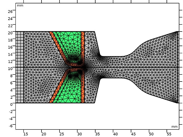
Fig. 2.
Mesh elements in middle part of channel.
.
Mesh elements in middle part of channel.
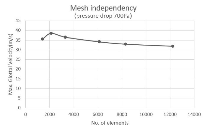
Fig. 3.
Mesh independence study.
.
Mesh independence study.
Table 2.
Flow rates in different inlet pressures for healthy and treated vocal folds
|
Case
|
Inlet pressure (Pa)
|
Flowrate (mL/s)
(healthy)
|
Flowrate (mL/s)
(treated)
|
| 1 |
700 |
249.97 |
205.09 |
| 2 |
800 |
293.32 |
231.46 |
| 3 |
900 |
337.71 |
259.95 |
| 4 |
1000 |
372.84 |
285.41 |
| 5 |
1100 |
417.99 |
313.26 |
Air flew to the channel with a varying inlet pressure between 700 and 1100 Pa with 100 Pa steps, representing different stages for normal phonation. The inlet pressures corresponded to Reynolds numbers between 284 and 450. For healthy VFs, an initial gap of 0.2mm was considered.2,8
Fig. 4A and 4B illustrate the glottal jet evolution besides the streamlines and maximum glottal velocity in healthy VFs for different inlet pressures of 700 and 1100Pa. By increasing the inlet pressure, maximum glottal speed rose, which represents a louder sound generation. Moreover, streamlines were more direct; hence, larger amounts of airflow could reach the oral cavity, and generated sound became more audible than of lower inlet pressures. On the other hand, the jet deflected more whenever the inlet pressure was lowered. Jet deflection was associated with the Coanda effect reported in the literature.2 This is due to the convergent-divergent geometry of the glottal area.
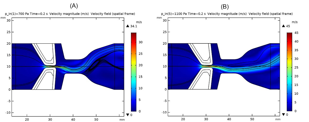
Fig. 4.
Glottal jet evolution, streamlines and maximum glottal velocity in healthy vocal folds: a) inlet pressure 700 Pa, b) inlet pressure 1100 Pa
.
Glottal jet evolution, streamlines and maximum glottal velocity in healthy vocal folds: a) inlet pressure 700 Pa, b) inlet pressure 1100 Pa
Treatments for unilateral VF paralysis include pushing the paralyzed VF to the centerline (medialization laryngoplasty) using surgery11,17 to push VFs toward the channel centerline. For this purpose, Silastic implants of Young’s modulus between 1 to 5 MPa,18 which are much stiffer in material properties and ideally in a shape of a healthy VF, are implanted. In this study, a silastic implant with a stiffness value of 5 MPa, and in the shape of a healthy VF body was used. The gap between VFs became narrower, and they recovered most of the sound generation ability. Fig. 5A and 5B illustrate the results after implanting Silastic into VFs, and the glottal jet evolution, streamlines and maximum glottal velocities were shown for 700 and 1100 Pa pressure drop across the channel.
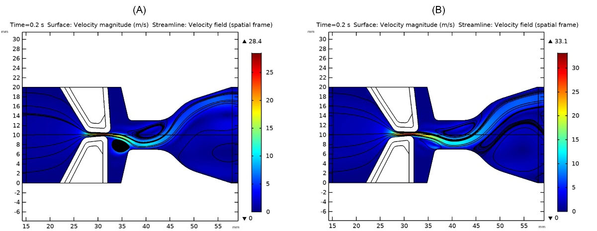
Fig. 5.
Glottal jet evolution, streamlines and maximum glottal velocity in treated vocal folds: a) inlet pressure 700Pa, b) inlet pressure 1100 Pa.
.
Glottal jet evolution, streamlines and maximum glottal velocity in treated vocal folds: a) inlet pressure 700Pa, b) inlet pressure 1100 Pa.
Generated vortices and lower velocities in the glottal area indicated the weaker sound generation since one VF had lost its motion and flow past VFs dissipated its energy due to generated vortices.
Glottal jet evolution at the end of one cycle also differed for various inlet pressures in healthy and treated VFs. The convergent-divergent channel flow in both true and false VFs made different flow behaviors, which directly impacted the quality and loudness of generated sound (see supplementary materials for the glottal jet evolution).
As normal phonation proceeds, which means higher glottal velocities and inlet pressures, the inlet flow becomes turbulent. However, in this study, it remained in the laminar region.19 By the end of the considered inlet pressure range, the flow reached transient region. Flow rates were also in agreement with the laminar flow assumption. Table 2 shows flow rates related to each inlet pressure for both healthy and treated (implanted) VFs.
Inlet velocity profiles for different pressure drops regarding normal phonation along the VF’s channel, as in Fig. 6, show that a pressure or velocity boundary condition at the inlet can be used interchangeably. Due to the air supply from the lungs for which the provided pressure is known for various phonation stages, this B.C. was applied. Equivalent inlet velocity profiles are shown in Fig. 6. This is in agreement with what has been done by Svácek and Horácek.7
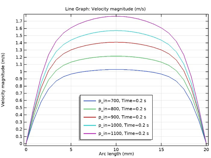
Fig. 6.
Inlet velocity profiles for different pressure drops regarding normal phonation along the vocal fold’s channel (in agreement with7).
.
Inlet velocity profiles for different pressure drops regarding normal phonation along the vocal fold’s channel (in agreement with7).
Shear stresses on top of each VF were also studied in both healthy and treated VFs. Table 3 compares the generated shear stresses for different pressure drops across the channel. It shows that in the case of UVFP and implant usage, no significant change occurs in the magnitude of shear stresses. The material properties for the desired implant can be chosen by studying the flow behavior in healthy VFs.
Table 3.
Shear stresses on top of a healthy and treated vocal fold during normal phonation
|
Case
|
Pressure drop (Pa)
|
Shear stress (healthy) (Pa)
|
Shear stress (treated) (Pa)
|
| 1 |
700 |
1.77 |
1.7 |
| 2 |
800 |
1.81 |
1.78 |
| 3 |
900 |
1.84 |
1.84 |
| 4 |
1000 |
1.83 |
1.85 |
| 5 |
1100 |
1.80 |
1.88 |
A witness point was located at (30.935,9.887) mm and was put on the VF cover to measure displacements of VFs. This region was first, in the glottal area and secondly, experienced the largest displacement. By increasing the inlet pressure, maximum displacements became larger. Hence, a louder and more audible sound was generated. In the case of UVFP, displacements became noticeably lower and almost motionless at the beginning of normal phonation. Table 4 illustrates maximum displacements and von Mises stresses for different inlet pressures in healthy and treated VFs. In both cases, the above parameters were calculated for the upper VF. As phonation proceeded, the one healthy VF in the UVFP case behaved similar to the healthy one.
Table 4.
Maximum displacements and stresses in healthy and treated vocal folds during normal phonation
|
Case
|
Inlet pressure (Pa)
|
Max. displacement
(mm)
|
Max. von Mises stress
(N/m2)
|
|
Healthy
|
Treated
|
Healthy
|
Treated
|
| 1 |
700 |
0.78 |
0.73 |
2260 |
2160 |
| 2 |
800 |
0.88 |
0.83 |
2520 |
2410 |
| 3 |
900 |
0.98 |
0.93 |
2760 |
2660 |
| 4 |
1000 |
1.04 |
1.02 |
2920 |
2880 |
| 5 |
1100 |
1.13 |
1.12 |
3150 |
3110 |
Deformations of VFs were 0.1 of their specific length,12 which is 1 centimeter. Hence, the application of small deformation theory was correct.
Furthermore, a negative pressure was observed in healthy VFs on the previous point. However, no negative pressure was seen in the case of UVFP. Fig. 7A and 7B show the variation of pressure with time in the witness point in both cases until the respected inlet pressure was fully employed.
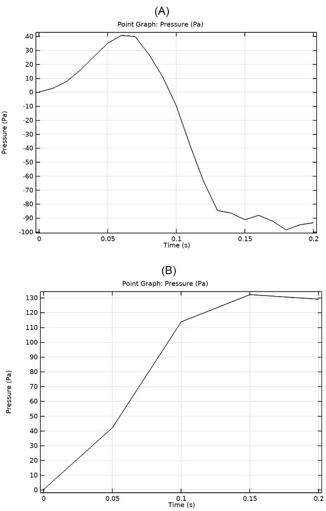
Fig. 7.
Variation of pressure with time in the witness point at 1100 Pa inlet pressure: (A) healthy vocal folds (B) treated UVFP case
.
Variation of pressure with time in the witness point at 1100 Pa inlet pressure: (A) healthy vocal folds (B) treated UVFP case
Negative pressure in healthy VFs at the witness point, which is in the glottal area, aided phonation by sucking air towards the epiglottis and out of the trachea. However, the above phenomenon did not happen in the UVFP case and even a positive pressure blocked the airway and made the sound generation weaker and more difficult than healthy VF. The amount increased as the inlet pressure rose, indicating that speech became more difficult for patients with UVFP as they continued to speak. With the increasing pressure in the glottal area, besides the diverging channel between true and false VFs, in the case of UVFP, flow separation also occured more severely than healthy VF and stall effect happened. Hence, it led to less flow to reach the oral cavity and caused breathiness of phonation.
The eigenfrequencies correspond to the resonant frequencies were calculated (the same for both VFs).9 Fig. 8A to 8C show the mode shapes and respective natural frequencies of vibrations for the upper VF. There were three eigenfrequencies in which the upper VF was excited. The first mode with the eigenfrequency of 69.633 Hz was the closest to the observed deformation of VFs in normal phonation investigated in the current study. For the case with the eigenfrequency of 187.31 Hz, the two VFs came in contact. Hence, the two higher frequency modes were out of the scope of this study.
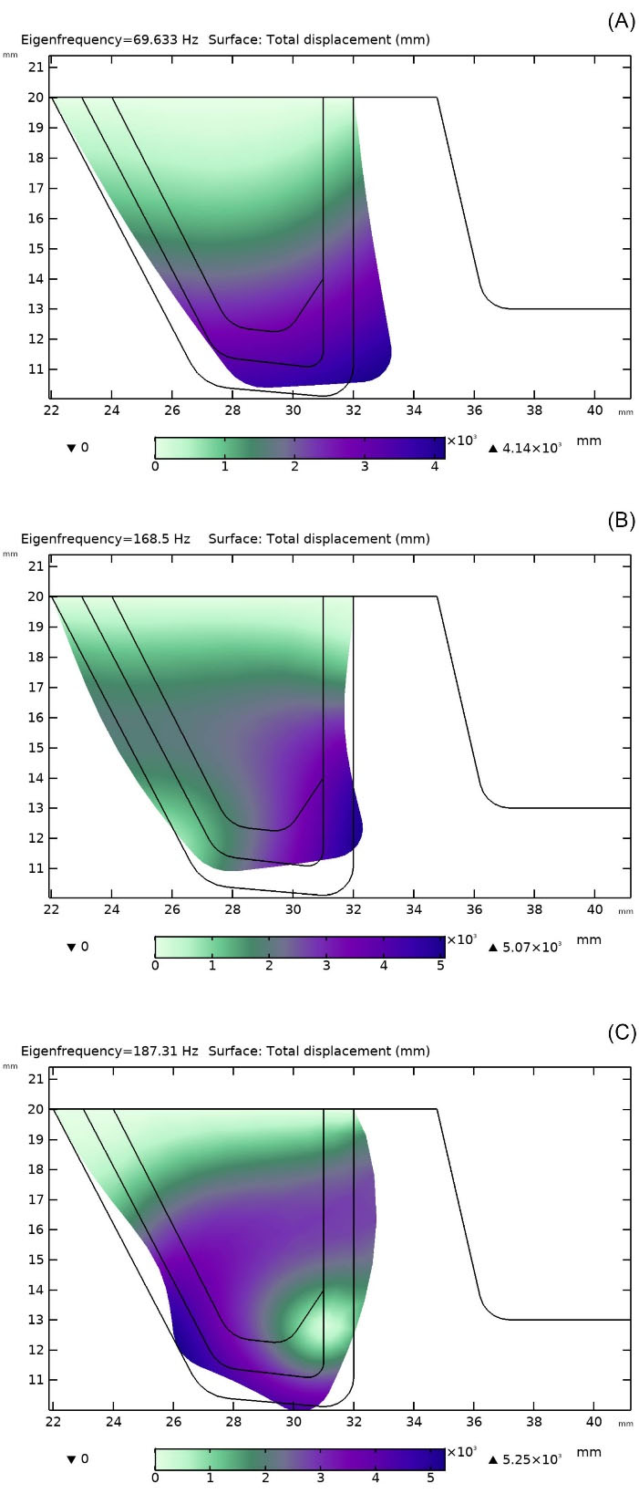
Fig. 8.
Mode shapes and respective eigenfrequencies for the upper vocal fold: (A) 69.63 Hz, (B) 168.5 Hz, (C) 187.31 Hz.
.
Mode shapes and respective eigenfrequencies for the upper vocal fold: (A) 69.63 Hz, (B) 168.5 Hz, (C) 187.31 Hz.
Conclusion
Phonation in healthy and treated unilaterally paralyzed VFs in two dimensions using FSI and varying inlet pressure were modeled. This model is applicable at the beginning of phonation, where supplied pressures from the lungs are still low and become less realistic as the phonation proceeds. For treating the UVFP, medialization laryngoplasty was employed. In this case, a surgery is needed to push the paralyzed VF to the centerline for phonation recovery. In the present work, both cases were studied, airflow over a pair of healthy and treated VFs regarding FSI. The results demonstrated that the flow parameters were recovered noticeably after using implants, which enhanced phonation. The maximum glottal velocities were around 75% of the healthy ones. Therefor, treating UVFP using medialization laryngoplasty is an effective method for recovering phonation with respect to the healthy VF. On the other hand, more vortices were generated, which dissipate the flow energy and hence a weaker sound is generated. Moreover, at the beginning of phonation, both healthy and treated VFs depicted similar flow behaviors in the larynx. By conducting studies like this, the outcome of laryngeal surgeries can be predicted and enhanced before doing any practical surgery.
Research Highlights
What is the current knowledge?
√ Unilateral vocal fold (VFs) paralysis happens when recurrent laryngeal nerve is paralyzed.
√ Medialization laryngoplasty is used to push the paralyzed Vs to the centerline to recover phonation.
What is new here?
√ FSI simulation of healthy and treated VFs with varying inlet pressure.
√ Study of flow parameters and phonation recovery after using implants.
Competing Interests
There is none to be disclosed.
Ethical Statement
There is none to be disclosed.
References
- Tsai MS, Yang YH, Liu CY. Unilateral Vocal Fold Paralysis and Risk of Pneumonia: A Nationwide Population-Based Cohort Study. Otolaryngol Head Neck Surg 2018; 158:896-903. doi: 10.1177/0194599818756285 [Crossref] [ Google Scholar]
- Mittal R, Zheng X, Bhardwaj R, Seo JH, Xue Q, Bielamowicz S. Toward a simulation-based tool for the treatment of vocal fold paralysis. Front Physiol 2011; 2:19. doi: 10.3389/fphys.2011.00019 [Crossref] [ Google Scholar]
- Murray PR, Thomson SL. Vibratory responses of synthetic, self-oscillating vocal fold models. J Acoust Soc Am 2012; 132:3428-3438. doi: 10.1121/1.4754551 [Crossref] [ Google Scholar]
- Zheng X, Bielamowicz S, Luo H, Mittal R. A computational study of the effect of false vocal folds on glottal flow and vocal fold vibration during phonation. Ann Biomed Eng 2009; 37:625-42. doi: 10.1007/s10439-008-9630-9 [Crossref] [ Google Scholar]
- Bagheri Sarvestani A, Goshtasbi Rad E, Iravani K. Numerical analysis and comparison of flow fields in normal larynx and larynx with unilateral vocal fold paralysis. Comput Methods Biomech Biomed Engin 2018; 21:532-540. doi: 10.1080/10255842.2018.1499898 [Crossref] [ Google Scholar]
- Sváček P, Horáček J. Finite element approximation of flow induced vibrations of human vocal folds model: Effects of inflow boundary conditions and the length of subglottal and supraglottal channel on phonation onset. Appl Math Comput 2018; 319:178-94. doi: 10.1016/j.amc.2017.02.026 [Crossref] [ Google Scholar]
- Švancara P, Horáček J, Martínek T, Švec JG. Numerical simulation of videokymographic images from the results of the finite element model. Proceedings 20th International Conference on Engineering mechanics; May 2014; Svratka, Czech Republic.
- Wang X, Jiang W, Zheng X, Xue Q. A computational study of the effects of vocal fold stiffness parameters on voice production. J Voice 2021; 35: 327.e1-327.e11. 10.1016/j.jvoice.2019.09.004.
- Li Z, Wilson A, Sayce L, Avhad A, Rousseau B, Luo H. Numerical and experimental investigations on vocal fold approximation in healthy and simulated unilateral vocal fold paralysis. Appl Sci 2021; 11:1-15. doi: 10.3390/app11041817 [Crossref] [ Google Scholar]
- Walton C, Carding P, Flanagan K. Perspectives on voice treatment for unilateral vocal fold paralysis. Curr Opin Otolaryngol Head Neck Surg 2018; 26:157-161. doi: 10.1097/MOO.0000000000000450 [Crossref] [ Google Scholar]
- Zhang Z, Chhetri DK, Bergeron JL. Effects of implant stiffness, shape, and medialization depth on the acoustic outcomes of medialization laryngoplasty. J Voice 2015; 29:230-5. doi: 10.1016/j.jvoice.2014.07.003 [Crossref] [ Google Scholar]
- Alipour F, Brucker C, D D. Alipour F, Brucker C, DCook D, Gommel A, Kaltenbacher M, Mattheus W, et alMathematical Models and Numerical Schemes for the Simulation of Human Phonation. Curr Bioinform 2011; 6:323-43. doi: 10.2174/157489311796904655 [Crossref] [ Google Scholar]
- Luo H, Mittal R, Zheng X, Bielamowicz SA, Walsh RJ, Hahn JK. An immersed-boundary method for flow-structure interaction in biological systems with application to phonation. J Comput Phys 2008; 227:9303-32. doi: 10.1016/j.jcp.2008.05.001 [Crossref] [ Google Scholar]
- Chang S, Tian FB, Luo H, Doyle JF, Rousseau B. The role of finite displacements in vocal fold modeling. J Biomech Eng 2013; 135:111008-111008. doi: 10.1115/1.4025330 [Crossref] [ Google Scholar]
- Sváček P, Horáček J. FE numerical simulation of incompressible airflow in the glottal channel periodically closed by self-sustained vocal folds vibration. J Comput Appl Math 2021; 393:113529. doi: 10.1016/j.cam.2021.113529 [Crossref] [ Google Scholar]
- Hirano M, Kakita Y, Ohmaru K, Kurita S. Structure and Mechanical Properties of the Vocal Fold. Speech and Language 1982; 7:271-297. doi: 10.1016/b978-0-12-608607-2.50015-7 [Crossref] [ Google Scholar]
- Frizzarini R, Gebrim EMMS, Imamura R, Tsuji DH, Moyses RA, Sennes LU. Individually customized implants for laryngoplasty - Are they possible. J Voice 2012; 26:619-622. doi: 10.1016/j.jvoice.2011.09.005 [Crossref] [ Google Scholar]
- Shakti S. Direct numerical simulation of human phonation [dissertation]. University of Illinois at Urbana-Champaign; 2017.
- Lessmann RC, Zhang Z. Fluid dynamics of the human larynx and upper tracheobronchial airways. Aerosol Sci Technol 1993; 19:133-156. doi: 10.1080/02786829308959627 [Crossref] [ Google Scholar]