BioImpacts. 8(2):91-98.
doi: 10.15171/bi.2018.11
Original Research
Design, fabrication, and implantation of tube-shaped devices for the treatment of salivary duct diseases
Diego Velasquez 1, 2, Laurent Chaunier 1, Sofiane Guessasma 1, Frédéric Faure 3, Alain Bizeau 4, Graciela Pavon-Djavid 5, Anne Meddahi-Pellé 5, Denis Lourdin 1, *
Author information:
1
INRA, UR1268 Biopolymères Interactions Assemblages, Rue de la Géraudière, Nantes, 44316, France
2
Ingennova Research Group, CES University. Calle 10A # 22 – 04. Medellín, Colombia
3
Service ORL et CCF, Hôpital Edourad Herriot, CHU de Lyon, 69437 Lyon, France
4
Hôpital Sainte Musse, Service d’ORL et de Chirurgie Cervico-Faciale, Toulon, France
5
INSERM, U1148 LVTS, Université Paris 13, Sorbonne Paris Cité 99 Ave Jean-Baptiste Clément, 93 430 Villetaneuse, France
Abstract
Introduction:
Starch-based materials were designed using a special extrusion die in order to obtain a tube-shaped device for application to salivary duct treatment in the field of endoscopy, i.e., sialendoscopy .
Methods:
Extrusion process was used to produce starch tubes. Mechanical properties of the dry tube before implantation were determined using an axial compression test. A finite element study was carried out to simulate the behavior of the hydrated tube under external axial pressure. Hydrolysis of these devices in a simulated salivary solution was studied, as well as its glycerol kinetics release. An animal short-term implantation model for salivary ducts was proposed as a feasibility study for starch tube-shaped devices.
Results:
A continuous production of regular and size-controlled tubes was obtained. The very small diameter obtained, less than 2 mm, corresponds to the requirement of being insertable in a human salivary duct using sialendoscopy guidewire. Finite element analysis showed that the starch tube can still support an external pressure higher than 0.2 MPa without irreversible damage. After 4 days of implantation, the host response is encouraging and the inflammatory response for this type of procedure remains normal.
Conclusion:
These devices were adapted to sialendoscopic guidewires and able to be implanted in the salivary ducts of pigs. If a longer lasting tube is required, the crystallinity of the starch material should be improved.
Keywords: Extrusion, Degradable device, Sialendoscopy, Starch, Tube
Copyright and License Information
© 2018 The Author(s)
This work is published by BioImpacts as an open access article distributed under the terms of the Creative Commons Attribution License (
http://creativecommons.org/licenses/by-nc/4.0/). Non-commercial uses of the work are permitted, provided the original work is properly cited.
Introduction
Starch is a natural, renewable and biodegradable polymer produced by many plants as a source of stored energy. It is the second most abundant biomass component in nature and can be found in plant roots, stalks, crop seeds and staple crops such as rice, corn, wheat, cassava, and potato.
1
It is a polyanhydroglucose that consists of two homologous polymers: linear amylose and hyper-branched amylopectin, whose molecular weights (Mw) range from 104 to 106 g mol−1 and from 107 to 109 g mol−1, respectively. Starch is widely used to develop biodegradable materials such as soluble films,
2,3
as well as innovative materials for biomedical applications.
4-6
Several methods are involved in the creation of starch-based devices, including fiber bonding methods like wet spinning,
7,8
as well as injection molding,
9
solvent casting
10,11
and extrusion.
12
Mechanical properties of starch-based materials can be modulated by the addition of a plasticizing agent.
13
A shape memory effect can also be obtained by controlling their thermo-mechanical history.
14,15
In our group, we have studied different compositions of extruded materials based on 2 starch botanical origins for their suitability for biomedical applications.
16
Due to its ability to crystallize during immersion in the physiological medium at 37°C, the modulus of extruded potato starch containing 20% glycerol stabilizes at about 1-2 MPa with limited swelling, which improves its durability. Moreover, this composition has been shown to have good tissue integration and is biodegradable, which makes it a good candidate for temporary implants.
16
In this study, we used these properties to design devices for application in the domain of sialendoscopy, which is a minimally invasive clinical technique allowing endoscopic endoluminal visualization. This technique is applied in both diagnostic and surgical treatment of salivary duct pathologies such as sialolithiasis, strictures, and stenosis.
6,17
After surgery, due to wall duct injury during surgery, the repair process could induce a salivary duct stenosis, particularly in the case of high inflammation.
18
To avoid this side effect in clinical practice, a medical device was used in order to keep the lumen open.
19
The technical requirements of the device include an initial rigidity so that it can be easily inserted at implantation time, and it has to be adapted to both individual anatomic variations (from 1.0 to 2.2 mm)
20
and the sialendoscopic materials.
21
Once inserted, it has to maintain the lumen and support the external pressure of the dilated duct. Several devices, including vascular stents,
22
hypospadias stents,
23
and sialo drains,
24
have been used but show major disadvantages since they are sutured in order to maintain their anatomical position. Others are not sutured and may become loose after implantation and trigger infection. In this context, there is a need for a device that is adapted to sialendoscopy instruments and guidewires, and that is mechanically resistant, biocompatible and bioresorbable for use in temporary applications.
The aim of this study was to design, produce and evaluate a potato-starch tube-shaped device for a sialendoscopy intervention. The tube is made using the extrusion process equipped with a die specially designed for tube manufacturing. The mechanical properties of the tube were determined before the implantation. Its mechanical behavior in conditions of use was simulated using finite element modeling based on the intrinsic mechanical properties of starch materials. This computational method was selected instead of finite volume computation to solve a structural mechanics problem. The latter computational method is more suitable for simulation of fluid behavior.
25
The calculation considered the evolution of starch material properties due to water absorption, from the implantation step to its service life once implanted. The tube was then exposed to a salivary solution flow to study its degradation. Finally, to assess the feasibility of implantation, it was tested on a pig, a large animal model.
Materials and Methods
Extrusion of the starch-based tube
Potato starch was purchased from Roquette (F-62 Lestrem, France). The initial moisture content was 15% (wb, the total wet basis). Glycerol (purity >98%, Merck, Germany) was used as a starch plasticizer. Prior to extrusion, the water content of the starch was adjusted up to 27%. Glycerol was added in order to obtain plasticized materials. The amount of plasticizer was 20% of the hydrated total mass of the preparation (the samples of potato starch containing 20% glycerol are referred to as PS-G20). The extruder used to produce the samples was a SCAMIA single-screw device (Rheoscam Type 20.11d, F-91 Crosne, France) set with a die specifically designed to produce starch tubes. The standard temperature profile was [100°C; 110°C; 110°C; 105°C], corresponding to the zones from the feeding zone to the die exit. Screw speed rotation was 20 rpm, and the specific mechanical energy was approximately 180 J.g-1. The temperature of the material at the exit of the extrusion was approximately 110°C, high enough to ensure the fusion of starch granules. After extrusion, tube samples were kept in a closed vessel containing a saturated solution of NaBr to maintain a relative humidity of 57% at 20°C and to achieve stable moisture content. Before in vivo testing, samples were packed in individual bags (Westfield Medical Limited, Midsomer Norton, UK) and were sterilized by γ-ray ionization (Ionisos, Sablé-sur-Sarthe, France) at a minimal standardized property dose of 25 kGy, according to international regulation ISO 11137.
Structural and mechanical characterization of tubes before immersion
The glass transition temperature of materials was determined from thermograms obtained by differential scanning calorimetry (DSC) in an automated T.A. Q100 instrument (T.A. Instruments, USA). Moisture content was assessed by a TGA 2050 thermogravimetric analyzer (T.A. Instruments, USA). The mechanical properties were measured in compression mode with a dynamometer (Instron Corporation, USA) on tubes of 1 cm in length, at a displacement rate of 5 mm.min-1.
Finite element analysis of the starch-based tube-shaped material behavior
Finite element computation was used to predict tube behavior until deterioration as a function of external pressure. Moreover, the evolution of material properties during an immersion that simulated body conditions was taken into account. A previous study showed the mechanical behavior of starch-based materials under physiological conditions (without enzymes).
16
All computations were performed using ANSYS structural analysis software (ANSYS, Canonsburg, PA, USA). The geometry was meshed using an irregular meshing scheme. Structural meshing was based on a tetrahedral structural solid element with a quadratic displacement behavior and ten nodes, where each node is capable of structural displacement in the three main directions. The mesh fineness was adapted to a typical element with a size of 200 µm in order to end up with a model size of 106 542 degrees of freedom (dof). The study of tube deformation requires the implementation of a constitutive law that takes irreversible straining into account. This was done here using a rate-independent plasticity model that assumes the plastic strain to develop instantaneously once a certain stress level, i.e., the yield criterion σY, is reached. This also means that plasticity is not dependent on the strain rate. Yielding occurs when the equivalent stress σe reaches the yield criterion. The equivalent stress is written as a function of the stress components. The yield conditions are presented in equation 1, where {σ} is the stress vector.
An isotropic hardening model is assumed to describe the uniform expansion of the von Mises yield surface. Loading conditions correspond to the surface loads Fs applied on the nodes belonging to the outer diameter of the tube. A constant pressure Σe is applied to these nodes and radially directed from the outer to the inner part of the tube.
The problem is solved iteratively to determine the displacement and straining of the tube for an increasing pressure. The change in tube diameter ΔD resulting from the radial displacement is described in equation 2. When the sum is performed over all nodal positions at the outer diameter of the tube, z is the coordinate position along the tube axis of symmetry, r is the radial distance from the center of the tube, R0 is the initial radius of the tube and Urz is the radial displacement, which is linked to the structural displacements in the Cartesian coordinate system using equation 3.
Degradation of the starch-based tube under flow conditions
In order to simulate salivary flow, a circulating system was designed using a pump (Nutricia Flocare Infinity Pump, Nutricia, the Netherlands), as shown in Fig. 1. A starch tube of PS-G20 (weight: 30 mg; length: 1 cm; outer diameter: 1.8 mm; and inner diameter: 0.8 mm) was inserted in the PVC tube (diameter: 2 mm) from the flow system and maintained at 37°C, as shown in Fig. 1. A salivary buffer was made according to ISO standard 10993-15. It was composed of Na2HPO4 (1.83 mM), NaCl (12 mM), KSCN (3.4 mM), KH2PO4 (1.47 mM), NaHCO3 (17.8 mM) and KCl (16 mM), with a pH adjusted to 7.2 +/- 0.2, and 0.25 mM CaCl2 was added to improve α-amylase activity. The concentration of porcine pancreatic α-amylase was 0.03 g/L according to the natural saliva composition. The salivary buffer began to circulate at a flow rate of 12 mL/h, representing the human saliva flow without stimulation. The buffer was collected at the exit of the system, (4 mL every 20 minutes per tube of the collector). The glycerol released and the carbohydrate hydrolysis was assayed in the collected solution. To determine glycerol concentration, samples were filtered using syringe-driven filters of 0.45 µm (Millipore, USA), and the glycerol was quantified by high-pressure liquid chromatography (HPLC, Waters, USA) with an HX 87H Aminex column (BioRad, USA) at 40°C, a flow rate of 0.7 mL/min and a pressure of 7.6 MPa. Different concentrations of glycerol were quantified as a function of time, allowing the calculation of glycerol released. Carbohydrate concentrations were determined by the sulfuric acid-orcinol colorimetric method.
26
The experiment was duplicated.
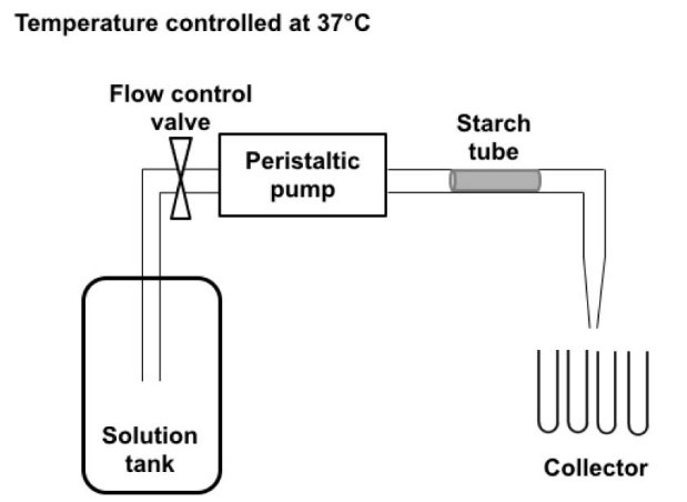
Fig. 1.
Diagram representing the circulating system containing the starch tube. The flow, regulated at 12 mL/min, is propelled by the peristaltic pump and goes from the solution tank through the starch tube for 48 h. Samples are collected in separate tubes with the help of an automatic collector that changes the collecting tube every 20 min after collecting 4 mL.
.
Diagram representing the circulating system containing the starch tube. The flow, regulated at 12 mL/min, is propelled by the peristaltic pump and goes from the solution tank through the starch tube for 48 h. Samples are collected in separate tubes with the help of an automatic collector that changes the collecting tube every 20 min after collecting 4 mL.
In vivo validation of the implantation model and histological study
In vivo experiments were held at the Institut de Chirurgie Expérimentale du Centre Léon Bérard, (Lyon, France) after the agreement of the local ethics committee (B 69388 0501). Two female pigs, 3 months old and weighing 35-40 kg (EARL Porcs du Plateau, 38940 Saint-Clair sur Galaure), were used as the animal model. Previous to implantation, an ultrasound evaluation was performed (Ecoscan Hitachi EUB405, 7.5 MHz) by immersing the tube into a beaker with water, allowing the identification of the tube in a solution. PS-G20 tubes with inner and outer diameters of 0.8 mm and 1.8 mm, respectively, and a length of 40 mm were inserted into sublingual salivary canals. Fifteen minutes prior to the implantation, intramuscular premedication of the animals was performed with a blend of Ketamine (15 mg/kg - Imalgene 1000 ND), Azaperone (2.2 mg/kg - Stresnil ND) and Atropine (0.5 mg). A 20G (11/10) catheter was inserted in the ear vein. Pigs were anesthetized with a blend of Zolazepam and Tiletamine (Zoletil 100 TM) via the catheter (5 mg/kg). They breathed freely without a breathing tube. The pigs were placed on their side and their mouths were kept open. The opening of the submandibular duct was identified. Progressive dilatation of the papilla was performed with salivary dilatators of progressively larger diameters. Sialendoscopy was performed with progressive endoluminal irrigation using a saline solution. An All-In-One Sialendoscope® from Karl Storz (Tuttlingen, Germany) equipped with a sialendoscope was used. The device was directly inserted into the dilated submandibular duct and then pushed further into the duct using a dilatator from the Karl Storz sialendoscopy kit. Post-surgical follow-up of the salivary duct was performed by echography using the same equipment described above. At day 4 after implantation, animals were anesthetized and euthanized with Zolazepam and Tiletamine (Zoletil 100). All of the tissue underneath the tongue was explanted and fixed in paraformaldehyde (4% in PBS). After fixation, the salivary duct and the surrounding tissue were collected, dehydrated and embedded in paraffin. Three-micron-thick sections were cut using a microtome (Microm Microtech, France) and stained with hematoxylin-phloxine-saffron (HPS). Digital images were obtained with a NanoZoomer 2.0 RS (Hamamatsu).
Results
Extrusion of the starch-based tube
The coupling of the die to the single screw extruder and the schema of the die specifically designed for manufacturing starch tubes are shown in Fig. 2A and B. The die, whose temperature is regulated at 105°C, is placed vertically at the exit of the extruder. The melted starch flows in a channel located on a side and fills a circular groove before flowing into the conic extremity of the die where the tube is shaped. The continuous production of regular and size-controlled devices is achieved by the action of gravity. The design of the die makes it possible to inject air in order to obtain large diameter tubes, as shown in Fig. 2C. For this study, tubes produced without air injection had an outer and inner diameter of 1.8 mm and 0.8 mm, respectively.
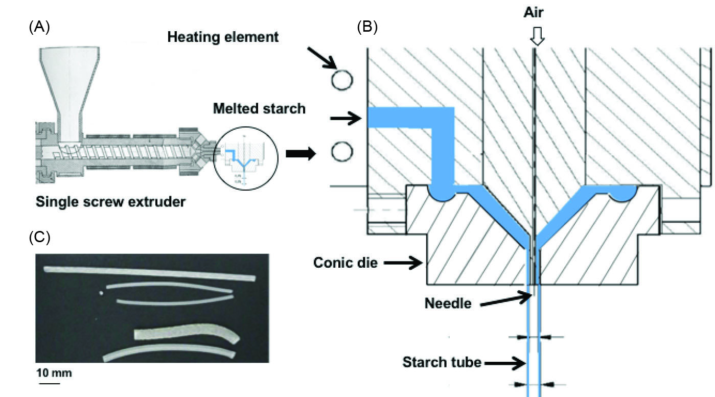
Fig. 2.
Production of starch tubes. (A) Single screw extruder equipped with the die designed for tube shaping. (B) Die scheme designed to fit a starch tube extrusion. The blue part corresponds to the region filled by melted starch. The air pressure introduced by the needle allows the regulation of the diameter of the tube. (C) Examples of different tubes obtained by controlling air pressure.
.
Production of starch tubes. (A) Single screw extruder equipped with the die designed for tube shaping. (B) Die scheme designed to fit a starch tube extrusion. The blue part corresponds to the region filled by melted starch. The air pressure introduced by the needle allows the regulation of the diameter of the tube. (C) Examples of different tubes obtained by controlling air pressure.
Structural and mechanical characterization of tubes before immersion
Characterization of starch tubes was performed after at least two weeks of moisture content stabilization in a controlled atmosphere of 57% humidity. The initial water content of the tube before immersion was 13% (total basis) and the glass transition measured by differential scanning calorimetry was 15°C. The difference between sterile and non-sterile materials was assessed beforehand, showing that γ-ray ionization had a weak influence on their mechanical behavior.
12
Starch materials, and particularly those containing glycerol, can be partially crystalline. X-ray diffraction carried out directly on tubes reveals an almost 100% amorphous organization, which probably means that the cooling and drying at the extrusion exit was rapid. Fig. 3 shows the force/strain curve determined under compression on the dry starch tube. The error bar indicated for each point corresponds to the standard deviation determined from five tests. The trend of the curve shown in Fig. 3 corresponds to a classic mechanical behavior of tube-shaped plastic materials submitted to a lateral compression between two flat parallel rigid platens and formerly reported by Nemat-Alla.
27
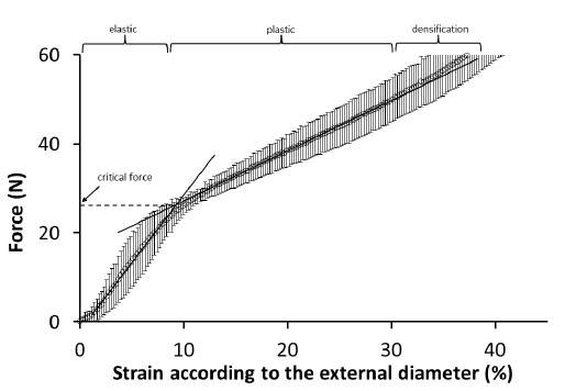
Fig. 3.
Determination of the critical force at compression of PS-G20 starch-based tubes.
.
Determination of the critical force at compression of PS-G20 starch-based tubes.
The tube is comprised of different zones: above the critical force at about 30 N, indicating the elastic limit, the tube is irreversibly deformed in the plastic domain, with the appearance of crazing in the vertical and horizontal diameters; above 50 N in the densification domain, the tube is collapsed and the lumen is closed.
Finite element analysis of the behavior of the starch-based tube-shaped device
Once implanted, the tube is under pressure from the dilated duct on its outer surface. A finite element modeling (FEM) approach was set up to calculate the deformation of the tube. Moreover, it is necessary to take the change in the mechanical properties of the starch material due to the effect of temperature and humidity changes into account. These changes were studied on PS-G20 and the experimental procedure and results are detailed in a previous paper.
16
In this previous study, the intrinsic mechanical properties of PS-G20 were determined on samples in the shape of a square, with a thickness on the same order as the tube, under a solicitation of compression at different immersion times in physiological media at 37°C. Two slopes were determined for three immersion times on the basis of the stress/strain curves obtained. The first slope refers to the elastic modulus EY. Beyond the yield stress value σY, the second slope is referred to as the tangent modulus ET. The full determination of starch behavior is based on the three mechanical quantities EY, σY and ET indicated as a supplementary table (see online supplementary file 1). The optimization of these mechanical data using the Finite element computation is provided as supporting data as well (see online Supplementary Fig. S1). The geometry and the dimensions of the virtual tube for finite element study are adapted according to the experimental layout with a typical outer diameter of 1.8 mm, an inner diameter of 0.8 mm and a length of 10 mm. The mechanical data previously determined are injected into the model, giving the results shown in Fig. 4. It also shows that the application of constant pressure along the outer diameter of the tube generates a symmetrical strain distribution, as illustrated by the strain intensity εINT counterplot. The largest strain levels are reached at the inner diameter of the tube. As both ends of the tube are set free, there is a tube extension in the longitudinal direction (Z) of 0.43 mm according to the displacement component UZ. Shearing strain takes place with the highest levels at 45° in an X-Y plane and constant magnitude along the longitudinal direction. All predicted evolutions reported in Fig. 5 show a common two-slope trend reflecting the elasto-plastic response of the tube and a tendency towards a decrease of the tube diameter for an increased pressure level. The first linear part of the curve response corresponds to the reversible shrinkage response.
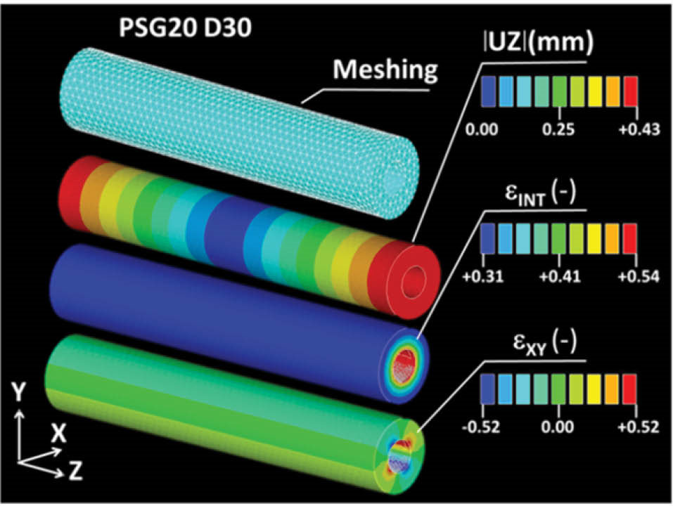
Fig. 4.
Finite element model to simulate the effect of an external pressure of 0.2 MPa on a starch tube after 30 days of immersion in a physiological media. UZ is the displacement component, εINT is the strain intensity, and εXY is the shearing strain in the XY plane.
.
Finite element model to simulate the effect of an external pressure of 0.2 MPa on a starch tube after 30 days of immersion in a physiological media. UZ is the displacement component, εINT is the strain intensity, and εXY is the shearing strain in the XY plane.
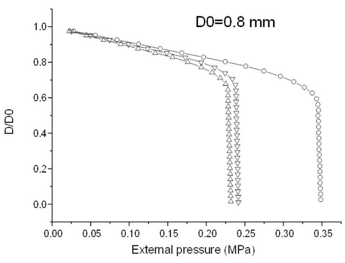
Fig. 5.
Depicts the ratio D/D0 of the internal diameter D vs. its initial value D0 as a function of the applied external pressure. The tube response is given for different immersion times (circle: 60 mn; triangle pointed upward: 240 min; triangle pointed downward: 30 days).
.
Depicts the ratio D/D0 of the internal diameter D vs. its initial value D0 as a function of the applied external pressure. The tube response is given for different immersion times (circle: 60 mn; triangle pointed upward: 240 min; triangle pointed downward: 30 days).
The intersection point indicates the onset of the irreversible straining of the tube. Any increase in pressure beyond this point permanently deteriorates the tube. Thus, the inflection point is a good criterion to set the maximum allowable pressure under in-service conditions. At this point, the internal diameter is still approximately 70% of its initial value. The immersion time lowers the tube performance and shifts back the critical pressure to lower levels. The calculated curves are quite similar as of 240 minutes (4 hours) of immersion, which means that equilibrium is reached. Moreover, according to results obtained in the previous study,
16
it seems that the tube would be a little more resistant after 30 days due to the crystallization of starch during immersion. At this stage, the starch tube can still support an external pressure higher than 0.2 MPa without irreversible damage.
Glycerol release and in vitro hydrolysis
The circulating system was set up to simulate the effect of a salivary flow in the tube. The first aspect concerns the release of the glycerol due to its low molecular weight and hydrophilic nature. Fig. 6 shows that the totality of the glycerol (20% total weight) introduced into the material is completely released after 100 minutes underflow. The second aspect concerns the enzymatic degradation of starch by the α-amylase introduced into the solution. Hydrolysis products were detected after 60 minutes of solution circulation. At 200 minutes, the kinetics of degradation is quasi-linear with the log of time. After 2 days (2880 minutes), 55% of the material is hydrolyzed and the tube is completely destructured. If the loss of glycerol is not a problem for the device performance, the potato starch enzymatic hydrolysis determined in vitro suggests a rapid deterioration in vivo.
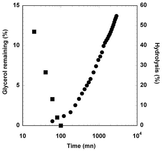
Fig. 6.
Evolution of remaining glycerol in samples (squares) and enzymatic hydrolysis (circles) under salivary buffer flow.
.
Evolution of remaining glycerol in samples (squares) and enzymatic hydrolysis (circles) under salivary buffer flow.
In vivo validation of the implantation model and histological study
Before implantation, starch tubes were sterilized by γ-ray ionization. Insertion of these devices was previously assessed in anatomical parts of euthanized pigs, performed in a living animal model for the first time. Implants were successfully performed in all animals, inserting the starch tube at least 10 mm deeper than the papilla, as indicated by the red arrow in the inset of Fig. 7A. After monitoring the echographic response of the tube immersed in water (Fig. 7B), the localization of the tube is verified by echography carried out just after implantation (Fig. 7C). During the 4 days of the implantation, no animal died and no implants were expelled from the salivary duct. By the last day of implantation, suffering or pain appeared to be minimal. No pus or infection was observed. A local inflammatory response was observed 24 hours after the implant took place and was still visible after 4 days near the papilla. For the histological study, a comparison was made between a non-implanted salivary duct (Fig. 7D and E) and an explant after 4 days of implantation (Fig. 7F and G). The normal histology of a healthy salivary duct presents a stratified epithelial tissue delineated by a slanted red line in Fig. 7E. It was possible to identify a local proliferation of cells in the implanted ducts that is consistent with the local inflammation observed macroscopically (Fig. 7G), although no vascularized tissue was damaged. Nonetheless, the surgical implantation procedure may cause slight damage to the epithelial tissue of the ducts, which explains the presence of cells embedded in the starch material.
28-30
Degradation products of the starch implants were observed to be embedded in this cellular proliferation (shown with red arrows in Fig. 7G). This means that the tube is probably fragmented after 4 days of implantation.
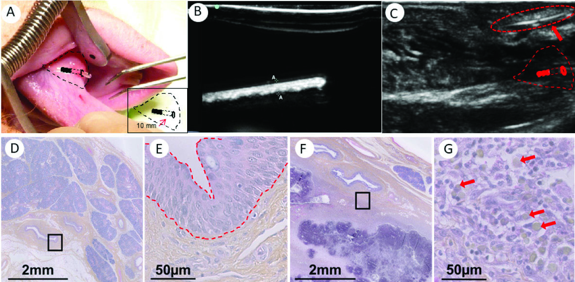
Fig. 7.
A: Implantation of a starch-extruded tube in the channel of the salivary gland of a pig (indicated by black lines); inset schema of implantation zone: the device was introduced into the channel at 10 mm from the entryway. B: Ultrasound images of the starch-extruded tube before implantation (immersed in water). C: Ultrasound images of the starch-extruded tube after implantation in the channel of the salivary gland of a pig (indicated by a red arrow). D: Regular anatomy of a salivary duct. The black square is magnified in E. Red slanted lines in E delineate the epithelial tissue of the salivary duct. F: Lumen of a salivary duct after 4 days of implantation of a starch-based tube, and the magnification in G shows the presence of cells (purple nucleus) and the remaining starch in the tissue (red arrows in G).
.
A: Implantation of a starch-extruded tube in the channel of the salivary gland of a pig (indicated by black lines); inset schema of implantation zone: the device was introduced into the channel at 10 mm from the entryway. B: Ultrasound images of the starch-extruded tube before implantation (immersed in water). C: Ultrasound images of the starch-extruded tube after implantation in the channel of the salivary gland of a pig (indicated by a red arrow). D: Regular anatomy of a salivary duct. The black square is magnified in E. Red slanted lines in E delineate the epithelial tissue of the salivary duct. F: Lumen of a salivary duct after 4 days of implantation of a starch-based tube, and the magnification in G shows the presence of cells (purple nucleus) and the remaining starch in the tissue (red arrows in G).
Discussion
The ability of starch to be processed as thermoplastic materials has been known for a long time.
14,31,32
To our knowledge, this is the first time that a tube made entirely of starch has been reported. The die was especially designed and allows the continuous production of regular and size-controlled tubes. The very small diameter obtained, less than 2 mm, corresponds to the requirement of being insertable in a human salivary duct by using sialendoscopy guidewire. The relatively high initial rigidity of the device facilitates its handling and insertion by the surgeon. Once inserted, and due to the strong hydration in situ the starch device naturally softens preventing duct injury. In addition to the softening of the material, the tube is subject to radial pressure induced by the dilated duct on its external surface. Because the effect of such a solicitation is difficult to measure by a real mechanical test, a finite element modeling (FEM) approach was set up to calculate the deformation of the tube. It appears that after 30 days of immersion, the starch tube can still support an external pressure higher than 0.2 MPa. The mechanical properties of the human salivary duct have never been reported, which makes difficult to compare this value in real conditions. To do this, it would be very helpful to establish the pressure-diameter (P-D) relationship of human salivary ducts using the same methodology set up by Sonoda et al applied to canine common carotid arteries.
33
We previously reported the implantation of starch-stents in pigs, without a study of evolution.
6
In this study, the implantation experiments and their evolution after 4 days brought different aspects out. The device is easily inserted with commercial tools and directly localized thanks to the very sharp and contrasted echographic imaging obtained on the starch materials. A local inflammatory response due to the surgical implantation procedure is observed on the first day, although no vascularized tissue was damaged.
28-30
The tube seems to be degraded after 4 days of implantation, due to the presence of salivary α-amylase. The enzymatic degradation of starch could be reduced by using a botanical source that is highly concentrated in amylose and that is less sensitive to α-amylase, e.g., amylomaize starch from corn.
6
If a longer implantation period is intended, the current formulations won’t last longer inside the duct. It will be of interest then to propose new formulations of starch-containing different types of plasticizers or treatments in order to enhance its mechanical behavior and durability in situ.
Conclusion
The objective of this study was to demonstrate the feasibility of an entirely starch-based tube for use in the treatment of salivary ducts. It has been shown that it was possible to produce such a device by extrusion whose millimeter size fits the specifications imposed by sialendoscopy guidewires and the implantation site. The tube can be easily implanted in salivary ducts in pigs thanks to commercial tools currently used by surgeons. After 4 days of implantation, the host response is encouraging and the inflammatory response for this type of procedure remains normal. For the future, it appears important to improve the composition and the control of the crystallinity of the material in order to reduce the high sensitivity of starch materials to α-amylase. Furthermore, the die setup in this study can be used for the production of tube-shaped devices with various dimensions. The methods developed in this work can be used to design and produce starch devices to correspond to specifications required for other implantation sites for temporary devices requiring biodegradable material.
Ethical approval
The current study involved the use of animal models. Hence, use of the two female pigs was evaluated and approved by the institutional ethics committee of the Experimental Surgery Institute registered with the French authorities (National Commission on Animal Experimentation).
Competing interests
There is no conflict of interests to be reported.
Acknowledgments
This work was funded by an ANR Emergence IRMAS grant (ANR-2010-EMMA-007), France. Mr. Velasquez would like to thank the Pays de la Loire Region for providing a partial Ph.D. scholarship. The authors are also grateful to R. Desirest, A. Beilvert, M. De Carvalho, S. Langonnet and O Thibaudeau for their precious support.
Supplementary Materials
Supplementary file 1 contains Table S1 and Figure S1.
(pdf)
Research Highlights
What is current knowledge?
simple
-
√ Starch is a versatile polysaccharide with applications in the
biomedical field.
-
√ Some formulations for starch-based materials are tissueintegrated
after implantation in vascularized tissues.
What is new here?
simple
-
√ Development and evaluation of starch tubes for biomedical
applications, particularly in otorhinolaryngology in a live
animal model.
-
√ Finite element analysis to predict the starch-tubes behavior
and its relation in salivary ducts strains.
References
- Buléon A, Colonna P, Planchot V, Ball S. Starch granules: structure and biosynthesis. Int J Biol Macromol 1998; 23:85-112. doi: 10.1016/S0141-8130(98)00040-3 [Crossref] [ Google Scholar]
- López OV, Lecot CJ, Zaritzky NE, García MA. Biodegradable packages development from starch based heat sealable films. J Food Eng 2011; 105:254-63. doi: 10.1016/j.jfoodeng.2011.02.029 [Crossref] [ Google Scholar]
- Peelman N, Ragaert P, De Meulenaer B, Adons D, Peeters R, Cardon L. Application of bioplastics for food packaging. Trends Food Sci Technol 2013; 32:128-141. doi: 10.1016/j.tifs.2013.06.003 [Crossref] [ Google Scholar]
- Torres FG, Troncoso OP, Gamucci O, Corvaglia S, Brunetti V, Bardi G. Immunological properties of Andean starch films are independent of their nanometric roughness and stiffness. Int J Biol Macromol 2015; 75:460-6. doi: 10.1016/j.ijbiomac.2015.02.008 [Crossref] [ Google Scholar]
- Liu M, Huang H, Wang K, Xu D, Wan Q, Tian J. Fabrication and biological imaging application of AIE-active luminescent starch based nanoprobes. Carbohydr Polym 2016; 142:38-44. doi: 10.1016/j.carbpol.2016.01.030 [Crossref] [ Google Scholar]
- Beilvert A, Faure F, Meddahi-Pellé A, Chaunier L, Guilois S, Chaubet F. A resorbable shape-memory starch-based stent for the treatment of salivary ducts under sialendoscopic surgery. Laryngoscope 2014; 124:875-881. doi: 10.1002/lary.24380 [Crossref] [ Google Scholar]
- Tuzlakoglu K1, Pashkuleva I, Rodrigues MT, Gomes ME, van Lenthe GH, Müller R. A new route to produce starch‐based fiber mesh scaffolds by wet spinning and subsequent surface modification as a way to improve cell attachment and proliferation. J Biomed Mater Res A 2010; 92:369-377. doi: 10.1002/jbm.a.32358 [Crossref] [ Google Scholar]
- Santos TC, Marques AP, Höring B, Martins AR, Tuzlakoglu K, Castro AG. In vivo short-term and long-term host reaction to starch-based scaffolds. Acta Biomater 2010; 6:4314-26. doi: 10.1016/j.actbio.2010.06.020 [Crossref] [ Google Scholar]
- Neves NM, Kouyumdzhiev A, Reis RL. The morphology, mechanical properties and ageing behavior of porous injection molded starch-based blends for tissue engineering scaffolding. Mater Sci Eng C 2005; 25:195-200. doi: 10.1016/j.msec.2005.01.009 [Crossref] [ Google Scholar]
- Arockianathan P, Sekar S, Sankar S, Kumaran B, Sastry TP. Evaluation of biocomposite films containing alginate and sago starch impregnated with silver nano particles. Carbohydr Polym 2012; 90:717-24. doi: 10.1016/j.carbpol.2012.06.003 [Crossref] [ Google Scholar]
- Requicha JF, Moura T, Leonor IB, Martins T, Muñoz F, Reis RL. Evaluation of a starch-based double layer scaffold for bone regeneration in a rat model. J Orthop Res 2014; 32:904-9. doi: 10.1002/jor.22609 [Crossref] [ Google Scholar]
- Beilvert A, Chaubet F, Chaunier L, Guilois S, Pavon-Djavid G, Letourneur D. Shape-memory starch for resorbable biomedical devices. Carbohydr Polym 2014; 99:242-8. doi: 10.1016/j.carbpol.2013.08.015 [Crossref] [ Google Scholar]
- Lourdin D, Coignard L, Bizot H. Influence of equilibrium relative humidity and plasticizer concentration on the water content and glass transition of starch materials. Polymer 1997; 38:5401-6. doi: 10.1016/S0032-3861(97)00082-7 [Crossref] [ Google Scholar]
- Véchambre C, Buléon A, Chaunier L. Understanding the mechanisms involved in shape memory starch: macromolecular orientation, stress recovery and molecular mobility. Macromolecules 2011; 44:9384-9. [ Google Scholar]
- Coativy G, Pontoire B, Lourdin D, Leroy E. Structural origin of stress and shape recovery in shape memory starch. Polymer 2015; 77:361-5. doi: 10.1016/j.polymer.2015.09.044 [Crossref] [ Google Scholar]
- Véchambre C, Buléon A, Chaunier L, Gauthier C, Lourdin D. Effect of crystallinity and plasticizer on mechanical properties and tissue integration of starch-based materials from two botanical origins. Carbohydr Polym 2015; 124:180-7. doi: 10.1021/ma202019v [Crossref] [ Google Scholar]
- Sabot JF, Gustin MP, Delahougue K, Faure F, Machon C, Hartmann DJ. Analytical investigation of salivary calculi, by mid-infrared spectroscopy. Analyst 2012; 137:2095-100. doi: 10.1039/c2an15924d [Crossref] [ Google Scholar]
- Koch M, Iro H, Zenk J. Sialendoscopy-based diagnosis and classification of parotid duct stenoses. Laryngoscope 2009; 119:1696-703. doi: 10.1002/lary.20522 [Crossref] [ Google Scholar]
- Koch M, Iro H, Klintworth N, Psychogios G, Zenk J. Results of minimally invasive gland-preserving treatment in different types of parotid duct stenosis. Arch Otolaryngol Head Neck Surg 2012; 138:804-10. doi: 10.1001/archoto.2012.1618 [Crossref] [ Google Scholar]
- Zenk J, Hosemann WG, Iro H. Diameters of the main excretory ducts of the adult human submandibular and parotid gland: A histologic study. Oral Surg Oral Med Oral Pathol Oral Radiol Endod 1998; 85:576-80. doi: 10.1016/S1079-2104(98)90294-3 [Crossref] [ Google Scholar]
- Marchal F. A Combined endoscopic and external approach for extraction of large stones with preservation of parotid and submandibular glands. Laryngoscope 2007; 117:373-7. doi: 10.1097/mlg.0b013e31802c06e9 [Crossref] [ Google Scholar]
- Kopec T, Szyfter W, Wierzbicka M, Nealis J. Stenoses of the salivary ducts-sialendoscopy based diagnosis and treatment. Br J Oral Maxillofac Surg 2012; 51:e174-7. doi: 10.1016/j.bjoms.2012.08.004 [Crossref] [ Google Scholar]
- Su CH, Lee KS, Tseng TM, Hung SH. Post-sialendoscopy ductoplasty by salivary duct stent placements. Eur Arch Otorhinolaryngol 2016; 273:189-95. doi: 10.1007/s00405-015-3500-5 [Crossref] [ Google Scholar]
- Liu D-G, Jiang L, Xie X-Y. Sialoendoscopy-assisted sialolithectomy for submandibular hilar calculi. J Oral Maxillofac Surg 2013; 71:295-301. doi: 10.1016/j.joms.2012.02.016 [Crossref] [ Google Scholar]
- Razavi SE, Sahebjam R. Numerical simulation of the blood flow behavior in the circle of Willis. BioImpacts 2014; 4:89-94. doi: 10.5681/bi.2014.008 [Crossref] [ Google Scholar]
- Tollier MT, Robin JP. Adaptation of the method sulfuric orcinol automatic determination of total neutral carbohydrates Terms of adaptation to extracts of vegetable origin. Ann Technol Agric 1979; 28:1-15. [ Google Scholar]
- Nemat-Alla M. Reproducing hoop stress–strain behavior for tubular material using lateral compression test. Int J Mech Sci 2003; 45:605-21. doi: 10.1016/S0020-7403(03)00115-2 [Crossref] [ Google Scholar]
- Jones KS. Effects of biomaterial-induced inflammation on fibrosis and rejection. Innate Adapt Immune Responses Tissue Eng 2008; 20:130-6. doi: 10.1016/j.smim.2007.11.005 [Crossref] [ Google Scholar]
- Anderson JM. Exploiting the inflammatory response on biomaterials research and development. J Mater Sci Mater Med 2015; 26:1-2. doi: 10.1007/s10856-015-5423-5 [Crossref] [ Google Scholar]
- Anderson JM, Rodriguez A, Chang DT. Foreign body reaction to biomaterials. Innate Adapt Immune Responses Tissue Eng 2008; 20:86-100. doi: 10.1016/j.smim.2007.11.004 [Crossref] [ Google Scholar]
- Leroy E, Decaen P, Jacquet P, Coativy G, Pontoire B, Reguerre AL. Deep eutectic solvents as functional additives for starch based plastics. Green Chem 2012; 14:3063-6. doi: 10.1039/c2gc36107h [Crossref] [ Google Scholar]
- van Soest JJG, Benes K, de Wit D, Vliegenthart JFG. The influence of starch molecular mass on the properties of extruded thermoplastic starch. Polymer 1996; 37:3543-52. doi: 10.1016/0032-3861(96)00165-6 [Crossref] [ Google Scholar]
- Sonoda H, Takamizawa K, Nakayama Y, Yasui H, Matsuda T. Small-diameter compliant arterial graft prosthesis: Design concept of coaxial double tubular graft and its fabrication. J Biomed Mater Res 2001; 55:266-276. doi: 10.1002/1097-4636(20010605)55:3<266::AIDJBM1014>3.0.CO;2-C [Crossref] [ Google Scholar]